VBOX Wheel Speed Sensors are fully wireless, eliminating the need for securing arms, power feeds, or data lines. This allows for effortless installation and precise wheel speed data capture.
We offer package options with or without a Wheel Speed Sensor Fixture Kit. The standard kit is compatible with 17 mm, 19 mm, and 21 mm wheel nuts, while larger sizes (22 mm and 23 mm) are available separately. Our sensor-only package provides a flexible solution for HGVs or vehicles that are incompatible with the standard mounting kit.
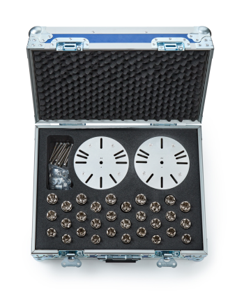
- Wheel nut split collets with collars (17 mm / 19 mm / 20 mm)
- Flange plate (mounting plate)
- Wheel mounting spacers
- Wheel mounting bolts (5 mm)
- Sensor mounting screws (3 mm)
- Allen key (5 mm)
- Allen key (3 mm)
- Wheel nut split collets with collars (17 mm / 19 mm / 20 mm)
- Flange plate (mounting plate)
- Wheel mounting spacers
- Wheel mounting bolts (5 mm)
- Sensor mounting screws (3 mm)
- Allen key (5 mm)
- Allen key (3 mm)

- Remove the collars from the wheel nut split collets.
- Place one split collets on each wheel nuts on the wheel.
IMPORTANT
The mounting plate must be level when installed.
In some instances, a locking nut may make its Wheel Nut Split Collet and Collar protrude more or less than on the other wheel nuts. To ensure that the mounting plate is level, you can do one of the following:
- Use spacers to make them all equal and level.
- Mount the plate on all the wheel nuts except the locking nut.
- Use a mallet (or similar tool) to seat the split collets fully on the wheel nuts. Make sure that the split collets sit level.
- Place the collars over the split collets.
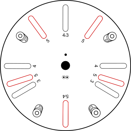
- Find the numbers next to the mounting slots on the flange plate.
- Use the slots that match the number of wheel nuts on the wheel (3, 4 or 5).
For example: If the wheel has 5 wheel nuts, use the slots marked 5.
IMPORTANT
You must always use the slots for the number of wheel nuts on the wheel and not the number of mounting bolts you are using.
- Align the selected mounting slots with the wheel nut locations.
- Put a wheel mounting spacer on each required wheel mounting bolt.
- Insert one wheel mounting bolt (5 mm) through each slot in the flange plate and into the top of the collar behind.
- Use the 5 mm Allen key to tighten the wheel mounting bolts.
As you tighten the wheel mounting bolts, the collars will clamp the split collets onto the wheel nuts.
- Tighten the wheel mounting bolts until the flange plate cannot move by hand. (No specific torque value required.)
- Select the correct Wheel Speed Sensor for the wheel position:
- RF = Right Front
- RR = Right Rear
- LF = Left Front
- LR = Left Rear
- Place the sensor on the flange plate. Align the sensor mounting holes with the raised screw threads on the flange plate.
- Insert the 4 sensor mounting screws (3 mm).
- Use the 3 mm Allen key to tighten the sensor mounting screws securely. (No specific torque value required.)
CAUTION
Make sure that the waterproof plug on each Wheel Speed Sensor is fully inserted into the charging port when you have completed the installation.
This video shows an example of the installation process.
- Connect one receive antenna for each Wheel Speed Sensor.
- Connect each antenna to the correct SMA port on the front panel (LF, LR, RF, RR)
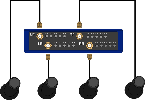
Place the receive antennas on the vehicle, close to the sensor that matches the SMA port on the Link Data Receiver.
IMPORTANT
- Make sure that the antenna is connected to the correct SMA port on the Link Data Receiver.
- Keep the antenna away from sources of radio interference (for example, 2.4 GHz devices).
- Mount the antenna as close to the sensors as possible.
- Make sure the antenna has a clear line of sight to the sensor.
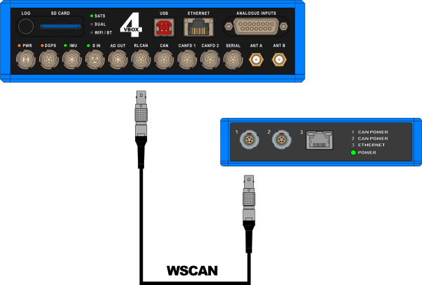
Connect the Link Data Receiver to VBOX 4:
- Connect one end of the WSCAN cable to one of the CAN/POWER ports on the rear panel of the Link Data Receiver.
- Connect the other end of the WSCAN cable to the RLCAN port on VBOX 4.
If you are using a different data logger than VBOX 4, click on the relevant heading below to view the connection information.
NOTE
You can download the .dbc file for the Wireless Wheel Speed Sensors here.
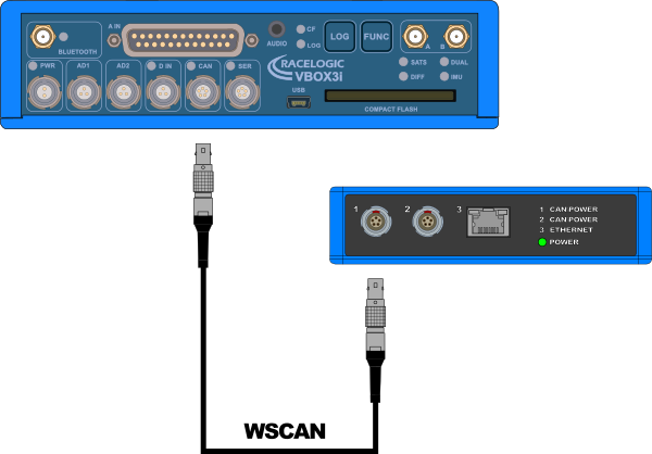
Connect the Link Data Receiver to VBOX 3i:
- Connect one end of the WSCAN cable to one of the CAN/POWER ports on the rear panel of the Link Data Receiver.
- Connect the other end of the WSCAN cable to the CAN port on VBOX 3i.
Find the complete configuration information for the Wireless Wheel Speed Sensors with VBOX 3i here.
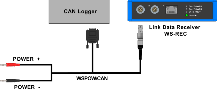
Connect the Link Data Receiver to a Third-Party data logger:
- Connect the Lemo connector on the WSPOW/CAN cable to one of the CAN/POWER ports on the rear panel of the Link Data Receiver.
- Connect the DB9 connector on the WSPOW/CAN cable to the CAN logger in the test system.
- Connect the Banana Plugs on the WSPOW/CAN cable to the power source.
Activate the sensors before the test:
- Swipe the Magnetic Switch over the top of each sensor.
- Wait for the Status LED to turn green. This confirms the sensor is active and ready for use.
IMPORTANT
Activate the sensors while the vehicle is stationary to allow bias calculation and zeroing.