You can access the menu by pressing the OK button. Use the Up and Down arrows to navigate through the menu and press the OK button to enter a submenu or change a setting. When you edit a setting, the Up and Down buttons will let you scroll through the available options for that setting and the OK button will confirm your selection. Use the Back button to exit a setting.
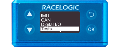
This menu can be used to configure brake test/lap timing settings.
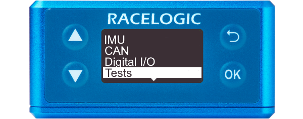
This menu can be used to configure brake test/lap timing settings.
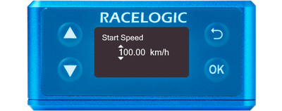
Defines the start speed at which the test will begin (100 km/h by default).
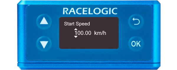
Defines the start speed at which the test will begin (100 km/h by default).
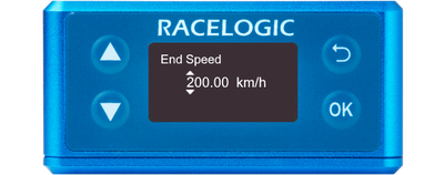
Defines the end speed at which the test will end (0 km/h by default).

Defines the end speed at which the test will end (0 km/h by default).
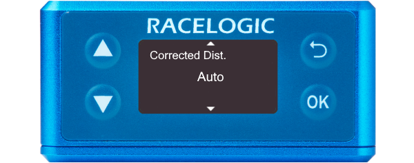
Auto corrected
This sets the speed sensor to use the nearest rounded 10 km/h speed when the trigger is activated.
For example, if the trigger speed was 104 km/h, then 100 km/h would be the nominated start speed for the corrected brake stop distance.
Value
85 km/h by default.
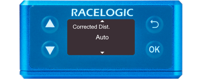
Auto corrected
This sets the speed sensor to use the nearest rounded 10 km/h speed when the trigger is activated.
For example, if the trigger speed was 104 km/h, then 100 km/h would be the nominated start speed for the corrected brake stop distance.
Value
85 km/h by default.
Defines the width of any gates set (25 m by default).
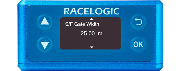
Defines the width of any gates set (25 m by default).
Defines the minimum amount of time needed between triggers for the second trigger to be valid. If a trigger is detected before this time, it will be ignored (1 s by default).
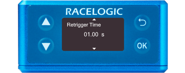
Defines the minimum amount of time needed between triggers for the second trigger to be valid. If a trigger is detected before this time, it will be ignored (1 s by default).

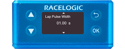
Defines the width of the pulse emitted when crossing a lap or split timeline (1 s by default).

Defines the width of the pulse emitted when crossing a lap or split timeline (1 s by default).
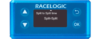
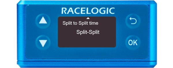
Determines whether the 'Split Time' CAN channel is either the total lap time at point of crossing the split line or the delta time between split lines.
SF - Split or Split - Split
Determines whether the 'Split Time' CAN channel is either the total lap time at point of crossing the split line or the delta time between split lines.
SF - Split or Split - Split