The following tables provide a list of channels capable of being calculated in each vehicle within an ADAS test.
- For 1 Vehicle Target testing, Racelogic refers to each vehicle as the ‘Subject Vehicle’ or the ‘Target Vehicle’. For example, under testing for adaptive cruise control, the lead vehicle will be the Target Vehicle, whilst the following vehicle (where the adaptive cruise control is being tested) is referred to as the Subject Vehicle.
- For 2 Target Vehicle testing, channel naming now changes such to indicate channels calculated with respect to, Target Vehicle 1 and Target Vehicle 2. As there are now three vehicles involved with this testing, the number of channels increases at the Subject Vehicle, this is reflected in the table below:
The vehicle separation channels calculated at the Target vehicle are essentially exactly the same as the channels calculated at the subject vehicle, except for the channels highlighted in yellow.
The channels highlighted in grey are not used in Static Point testing. These are listed to ensure continuity of the Racelogic report generator application, which uses channel ordering as its sort function.
Channel name definition. Where the channel name is not obvious, then it is made up of three parts:

- The first part is the parameter type i.e. LngR = Longitudinal Range
- The second part indicates which vehicle heading is being used in the calculation of this parameter i.e. sv = subject vehicle
- The last part indicates which vehicle is parameter is being calculated with reference to, i.e. tg1 = Target Vehicle 1
| Target 1 | Target 2 | Channel Description | Units |
|---|---|---|---|
| Range_tg1 | Range_tg2 | Direct Distance between Subject and Target vehicle | m |
| LngRsv_tg1 | LngRsv_tg2 | Longitudinal distance between the Subject and Target Vehicles measured in the direction of the Subject Vehicle heading | m |
| LatRsv_tg1 | LatRsv_tg2 | Lateral distance between the Subject and Target Vehicles measured at right angles to the Subject Vehicle heading | m |
| LngRref_tg1 | LngRref_tg2 | The longitudinal difference between the Subject and Target Vehicles based on the heading of the test track | m |
| LatRref_tg1 | LatRref_tg2 | The lateral difference between the Subject and Target Vehicles based on the heading of the test track | m |
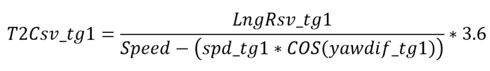
| T2Csv_tg1 | T2Csv_tg2 | Time to Collision with Target Vehicle derived from LngRsv-tg1 and LngSsv–tg1 channels | s |
| T2C2sv_tg1 | T2C2sv_tg2 | Time to Collision with a decelerating Target Vehicle derived from the LngRsv-tg1, LngSsv-tg1 and Accel-tg1 channels | s |
| RelSpd_tg1 | RelSpd_tg2 | The relative speed between the Subject and Target Vehicles | km/h |
| LngRtg-tg1 | LngRtg-tg2 | Longitudinal distance between the Subject and Target Vehicles measured in the direction of the Target Vehicle heading | m |
| LatRtg-tg1 | LatRtg-tg2 | Lateral distance between the Subject and Target Vehicles measured at right angles to the Target Vehicle heading | m |
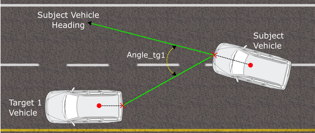
| Angle_tg1 | Angle_tg2 | Angle to the Target Vehicle with respect to the heading of the Subject Vehicle | ° |
| Latdif_tg1 | Latdif_tg2 | The difference between Subject Vehicle and Target Vehicle latitude | min |
| Lngdif_tg1 | Lngdif_tg2 | The difference between Subject Vehicle and Target Vehicle longitude | min |
| Spd_tg1 | Spd_tg2 | Target Vehicle course over ground speed | km/h |
| Spd_sv | N/A | Subject Vehicle course over ground speed | km/h |
| Accel_tg1 | Accel_tg2 | Target Vehicle acceleration calculated from Target Vehicle speed and time | g |
| LngSsv_tg1 | LngSsv_tg2 | The speed between the Subject and Target Vehicles in the longitudinal direction, with respect to Subject vehicle heading | km/h |
| LatSsv-tg1 | LatSsv_tg2 | The speed between the Subject and Target Vehicles in the lateral direction, at right angles to the Subject vehicle heading | km/h |
| Status_tg1 | Status_tg2 | The DGPS status of the Target vehicle VBOX | N/A |
| Status_sv | Status_sv | The DGPS status of the Subject vehicle VBOX | N/A |
| LkTime_tg1 | LkTime_tg2 | Rolling time sent over 2.4 GHz Radio Link, used to indicate the quality of radio link between vehicles | N/A |
| LkTime_sv | N/A | Rolling time sent over 2.4 GHz Radio Link, used to indicate the quality of radio link between vehicles | N/A |
| App_Mode | App_Mode | The current operating mode of the Subject VBOX | N/A |
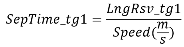
| SepTim_tg1 | SepTim_tg2 | The time it would take the Subject Vehicle to travel across the Vehicle separation distance at its current speed | s |
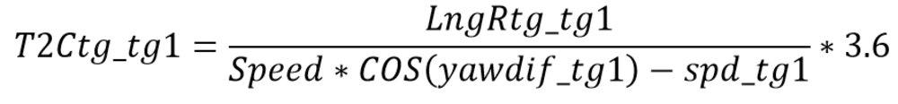
| T2Ctg_tg1 | T2Ctg_tg2 | Time to Collision with Target Vehicle, derived from the LngRtg-tg1 and Target vehicle long range speed | s |
| Yawdif_tg | Yawdif_tg2 | This angle is the difference between subject and target vehicle headings | ° |
| YawRat_tg1 | YawRat_tg2 | YAW rate of the Target vehicle, only available when an IMU is connected to the VBOX in the target vehicle | °/s |
| Pntsv_tg1 | Pntsv_tg1 | The current Subject vehicle contact point being referenced in the Subject to target vehicle ADAS calculations | N/A |
| Pnttg1_sv | Pnttg2_sv | The current Target vehicle contact point being referenced in the Subject to target vehicle ADAS calculation | N/A |
Longitudinal and Lateral Range with respect to subject vehicle heading.

NOTE
The LngRsv and LatRsv values are calculated from offset points on each respective vehicle. Details of how to apply these offsets is provided in the Quick Start Guide.
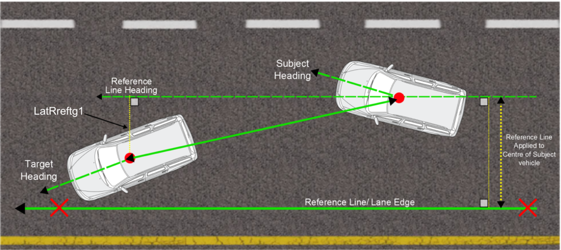
Longitudinal and lateral difference between two vehicles based on an external reference heading.
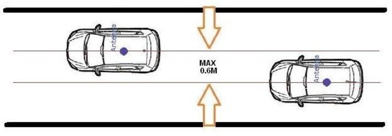
It is a requirement of the National Highway Traffic Safety Administration “Forward Collision Warning System NCAP Confirmation Test March 2012” confirmation tests that the Subject Vehicle (SV) remains within 0.6 m of the centre line of the Target Vehicle (in the standard referred to as Principle Other Vehicle - POV).
If this Lateral Range channel was based purely on vehicle heading then the resultant value would be extremely susceptible to noise. Small fluctuations in the Subject or Target Vehicle heading will results in fluctuations in Lateral Range greater than the NHTSA standard, the following example demonstrates this principle:
Heading fluctuation of 0.5° over a vehicle separation of 100 m:
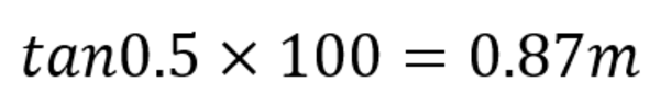
By using a Reference lane heading, a very stable Lateral Range channel is generated.
Longitudinal and Lateral Range with respect to target vehicle heading.

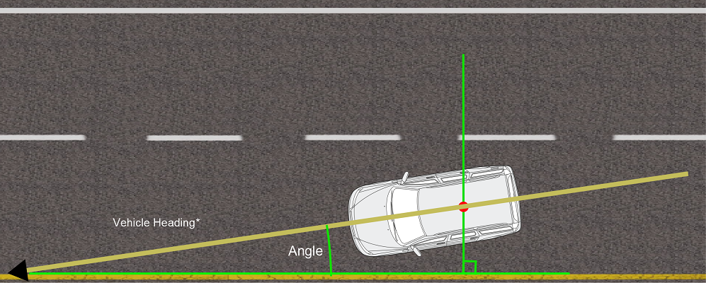
Angle to the Target Vehicle with respect to the heading of the Subject Vehicle.
Time to collision based on Longitudinal Range from Subject Vehicle to Target Vehicle based on Subject Vehicle heading and Longitudinal Speed.
T2Csv_tg1 example:
Time to collision taking into account a decelerating target vehicle.
NHTSA provide the following equation to account for a decelerating target vehicle in test 2 of their FCWS NCAP confirmation test.3
T2C2sv_tg1 example:
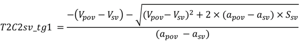
- Vpov = Velocity of Principle Other Vehicle (Target Speed)
- Vsv = Velocity of Subject Vehicle (Speed)
- apov = Acceleration of Principle Other Vehicle (Target Accel)
- asv = Acceleration of Subject Vehicle (Accel)
- Ssv = Longitudinal distance from Subject Vehicle to Target Vehicle (LngRange)
Time to collision based on Longitudinal Range from Subject Vehicle to Target Vehicle based on Target Vehicle heading and Target Vehicle longitudinal Speed.
T2Ctg_tg1 example:
This channel is a time based incremental value based on Target Vehicle UTC time. A good link will show a trace incrementing every 10 ms with no drops to zero. Once this value reaches 65535 it is reset to zero.
Link Time is a good indicator of ADAS radio link quality, If this incremental count drops out and falls to zero then it is a likely indication that the ADAS radio link has intermittently failed.
The VBOX ADAS system will suffer occasional single sample drops outs, which are acceptable but larger periods of time with full or intermittent drop outs are an indicator of a Radio problem that needs addressing.
This channel indicates the current operating mode of the VBOX.
| App Mode Value | Description |
|---|---|
| 1 | Normal |
| 2 | Target |
| 4 | Subject |
| 8 | Static |
| 10 | Lane departure - lane 1 |
| 0x50 | Lane departure - lane 2 |
| 0x90 | Lane departure - lane 3 |
For Adaptive Cruise control testing; time it would take the Subject Vehicle to travel across the Vehicle separation distance at its current speed.
SepTim_tg1 example:
The following tables provide a list of channels capable of being calculated in each vehicle within an ADAS test.
Channel name definition. Where the channel name is not obvious, then it is made up of three parts:
- The first part is the parameter type i.e. LngR = Longitudinal Range
- The second part indicates which vehicle heading is being used in the calculation of this parameter i.e. sv = subject vehicle
- The last part indicates which vehicle is parameter is being calculated with reference to, i.e. tg1 = Target Vehicle 1
| Subject | Target 1 | Target 2 | Target 3 | Channel Description | Units |
|---|---|---|---|---|---|
| Range_tg1 | Range_tg1 | Range_tg2 | Range_tg3 | Direct Distance between Subject and Target vehicles | m |
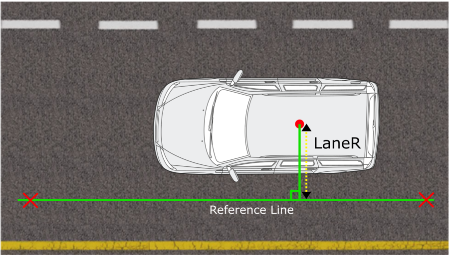
| LaneR_sv, LaneR_tg1, LaneR_tg2, LaneR_tg3 | LaneR_tg1 | LaneR_tg2 | LaneR_tg3 | Lateral distance between the vehicle antenna and the reference line measured at right angles to the reference line | m |
| LngRsv_tg1, LngRsv_tg2, LngRsv_tg3 | LngRsv_tg1 | LngRsv_tg2 | LngRsv_tg3 | Longitudinal distance between the Subject and Target Vehicles measured in the direction of the Subject Vehicle heading | m |
| LatRsv_tg1, LatRsv_tg2, LatRsv_tg3 | LatRsv_tg1 | LatRsv_tg2 | LatRsv_tg3 | Lateral distance between the Subject and Target Vehicles measured at right angles to the Subject Vehicle heading | m |
| LngRef_tg1, LngRef_tg2, LngRef_tg3 | LngRef_tg1 | LngRef_tg2 | LngRef_tg3 | Longitudinal distance between the Subject and Target Vehicles measured in the direction of the reference line heading | m |
| LatRef_tg1, LatRef_tg2, LatRef_tg3 | LatRef_tg1 | LatRef_tg2 | LatRef_tg3 | Lateral distance between the Subject and Target Vehicles measured at right angles to the reference line heading | m |
| Angle_tg1, Angle_tg2, Angle_tg3 | Angle_tg1 | Angle_tg2 | Angle_tg3 | Angle to the Target Vehicle with respect to the heading of the Subject Vehicle | ° |
| Status_sv, Status_tg1, Status_tg2, Status_tg3 | Status_sv, Status_tg1, Status_tg2, Status_tg3 | Status_sv, Status_tg1, Status_tg2, Status_tg3 | Status_sv, Status_tg1, Status_tg2, Status_tg3 | The DGPS status of the vehicle VBOXs | N/A |
| LkTime_tg1, LkTime_tg2, LkTime_tg3 | LkTime_tg1 | LkTime_tg2 | LkTime_tg3 | Rolling time sent over 2.4 GHz Radio Link, used to indicate the quality of radio link between vehicles | N/A |
| LnRtg1_tg1, LnRtg1_tg2, LnRtg1_tg3 | LnRtg1_tg1 | LnRtg1_tg2 | LnRtg1_tg3 | Longitudinal distance between the Subject and Target Vehicles measured in the direction of the Target Vehicle 1 heading | m |
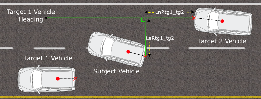
| LaRtg1_tg1, LaRtg1_tg2, LaRtg1_tg3 | LaRtg1_tg1 | LaRtg1_tg2 | LaRtg1_tg3 | Lateral distance between the Subject and Target Vehicles measured at right angles to the Target Vehicle 1 heading | m |
| Spd_tg1, Spd_tg2, Spd_tg3 | N/A | N/A | N/A | Target Vehicle course over ground speed | km/h |
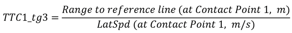
| TTC1_tg3 | N/A | N/A | TTC1_tg3 | Time for the front most contact point of Target Vehicle 3 to cross the reference line | s |
A number of the parameters shown in the table above are outlined in schematics below in order to give a clear visualisation of how they are calculated.
Channels not explained below can be viewed within the Vehicle Separation Measured Parameters section above.
Lateral distance between the vehicle antenna and the reference line measured at right angles to the reference line.
Lateral distance between the Subject and Target Vehicles measured at right angles to the Target Vehicle 1 heading.
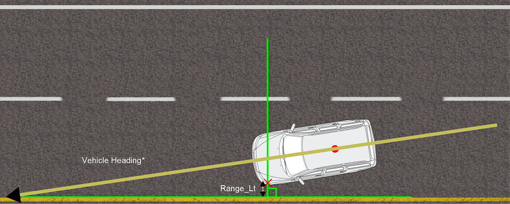
Time to cross the reference line calculated from the front most contact point of Target Vehicle 3.
Assuming Contact Point 1 is the front most contact point:
The following table provides a list of extra channels capable of being logged in the Subject Vehicle during a lane departure warning system test.
| Channel Name | Channel Description | Units |
|---|---|---|
| Range_FL | Lateral Distance to Line from vehicle front left point | m |
| Range_FR | Lateral Distance to Line from vehicle front right point | m |
| Range_RL | Lateral Distance to Line from vehicle rear left point | m |
| Range_RR | Lateral Distance to Line from vehicle rear right point | m |
| TTC_FL | Time To Line cross, wrt to vehicle front left point | s |
| TTC_FR | Time To Line cross, wrt to vehicle front right point | s |
| TTC_RL | Time To Line cross, wrt to vehicle rear left point | s |
| TTC_RR | Time To Line cross, wrt to vehicle rear right point | s |
| LatSpd_FL | Lateral speed toward line wrt to vehicle front left point | km/h |
| LatSpd_RR | Lateral speed toward line wrt to vehicle rear right point | km/h |
| LatSpd_RL | Lateral speed toward line wrt to vehicle rear left point | km/h |
| LatSpd_FR | Lateral speed toward line wrt to vehicle front right point | km/h |
| Angle | The Angle between the vehicle heading and the tangent of the reference lane at the point where range is calculated | ° |
A number of the parameters shown in the table above are outlined in schematics below in order to give a clear visualisation of how they are calculated.
The value for Range is the shortest perpendicular distance between the Front Left, Front Right, Rear Right or Rear Left offset point and the surveyed lane.

Time to cross the reference lane calculated from the Front Left, Front Right, Rear Right or Rear Left offset point range and lateral speed.
Front right offset example:
TTC_FR = Range_FR (m)/LatSpd_FR (m/s)
Lateral speed of the Front Left, Front Right, Rear Right or Rear Left offset point with respect to the marked lane edge.
Front Left offset example:
LatSpd_FL = Vfwd * Sin(α)
- Vfwd = GPS velocity (course over ground)
- α = Lane edge Heading – Heading at Vehicle offset point.
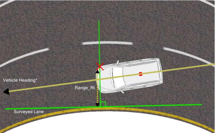
The value of Angle is the angle between the vehicle heading and the tangent of the surveyed lane at the shortest perpendicular distance to the GPS antenna.
When testing a Lane Departure Warning System around a curved lane the VBOX firmware takes measurements from the corner position to the nearest perpendicular tangent line to the curved lane edge, as shown belo
The following table provides a list of extra channels capable of being logged in the Subject Vehicle during a multi static point test.
| Channel Name | Description | Units |
|---|---|---|
| ID (1-5) | The point number of the feature currently occupying ID 1/2/3/4/5 | N/A |
| Range (1-5) | The direct distance between the measurement point and the feature in ID 1/2/3/4/5 | m |
| Lat_Range (1-5) | The Lateral distance between the measurement point and the feature in ID 1/2/3/4/5 measured at right angles to the subject vehicle's heading | m |
| Lng_Range (1-5) | The Longitudinal distance between the measurement point and the feature in ID 1/2/3/4/5 measured in the direction of the subject vehicle's heading | m |
| Angle (1-5) | The angle to the feature in ID 1/2/3/4/5 with respect to the subject vehicles heading | ° |