The VBOX Speed Sensor should be secured inside the vehicle to stop it from moving when the vehicle is in motion.
The base plate has M3 screw holes along its length that you can use if you want to bolt it directly to a mounting surface in the vehicle.

The VBOX Speed Sensor should be secured inside the vehicle to stop it from moving when the vehicle is in motion.
The base plate has M3 screw holes along its length that you can use if you want to bolt it directly to a mounting surface in the vehicle.
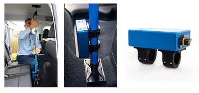
Alternatively, the Racelogic Mounting pole is compatible so you can mount the unit vertically. Contact vbox@racelogic.co.uk for more information or to order a mounting arm (RLACS212-V2) and/or mounting bracket (RLACS291).
Appropriate placement of the GNSS antenna is crucial to the quality of the data that is being recorded.
Be aware of objects that can shadow the antenna or block the signal to the antenna. Some objects can also reflect signals which can send weaker GNSS signals to the antenna. This is called multipath, and these reflections can disturb the signal in an unpredictable way.
If an antenna is not mounted on a large enough ground plane, multipath reflections can also come from the ground beneath the antenna.
Note: You can find in-depth information about how to place the antenna on a vehicle and how to use the satellite elevation mask here.
Note: It is important that you do not use force when connecting and disconnecting the loom to the VBOX Speed Sensor.

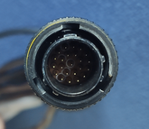
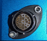

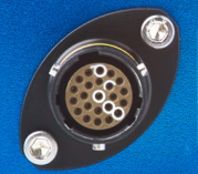
- Look at the connectors on both the loom and the VBOX Speed Sensor.
- Locate the different-sized inner notches on the loom's connector and line them up with the equivalent notches on the unit's connector.
- Note the outer notches on the connector.


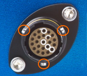
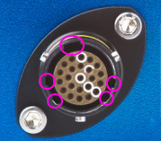

Push the connectors gently together and twist the outer ring on the loom's connector until it slots in place and locks the connection.
Note the notches on the connectors as illustrated above. Twist the loom's connector while you gently pull it away from the unit.