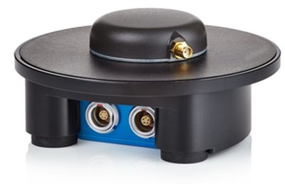
If you are using an external IMU04 in conjunction with VBOX 3iS, it can be roof mounted, fixed rigidly to a vehicle through the fixing holes or secured using a telescoping mounting arm. It should be mounted in the direction of travel and level with the ground.
The easiest method of mounting the IMU is by placing it directly on the vehicle roof, co-located with the GNSS antenna.
The IMU roof mount should be mounted on a braced, stable part of the roof, such as the area over the A or B Pillar.
Care should be taken to avoid placing the mount in a half-braced position, where the front or rear is on a supported part of the roof, and the opposite end is on a flexible location. The potential pivot can induce a pitch rate oscillation that will influence the accuracy of the results.
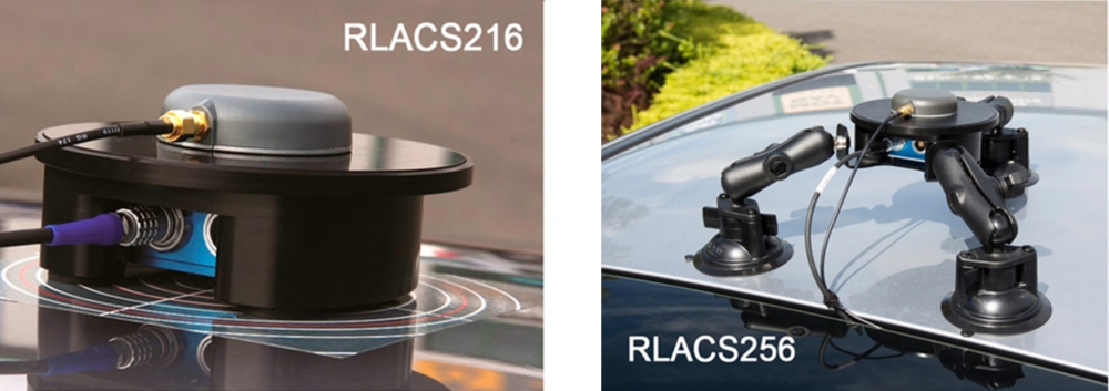
Magnetic base (RLACS216)

Magnetic base (RLACS216)
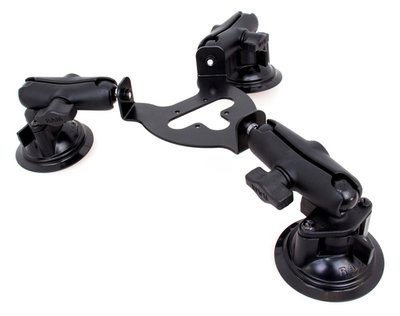
Suction mount (RLACS256)
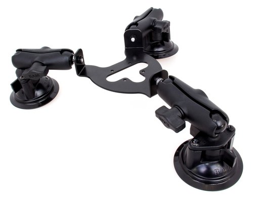
Suction mount (RLACS256)
Please contact vbox@racelogic.co.uk for more information, or to order an IMU Roof Mount.
When a roof mount is enabled using the VBOX Setup Software, the Front Panel of the unit or using the VBOX Manager, an automatic 1 m z offset is added, translating the filtered speed down into the vehicle towards the centre of gravity. This can be changed by entering translation values within the VBOX Setup Software, the Front Panel of the unit or using the VBOX Manager.
Customer-required translation measurements should be made in the same plane as to which the IMU is mounted (i.e. perpendicular to the IMU base, not straight down to the ground).


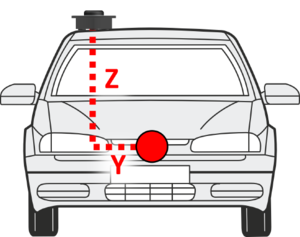
When using either a fixed mounting point or the mounting arm, you must measure the relative position of the antenna in relation to the IMU to at least within +/- 5 cm.
These will be the x,y, and z offset values from the antenna to the IMU04.
These distances must then be entered into the VBOX 3iS via inputting directly using the VBOX Setup Software, the Front Panel of the unit or using the VBOX Manager.
- Connect IMU04 to VBOX 3iS, ensuring the unit is powered.
- Connect VBOX 3iS to a computer using the supplied loom, connect an RLCAB001 cable to the 'CONFIG' lead and connect the serial plug to the computer serial port – this can be done via a serial > USB converter if required.
- Open VBOX Setup and connect to VBOX 3iS by selecting the correct COM Port.
- Select the 'IMU' menu and then the 'Settings' tab.
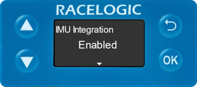
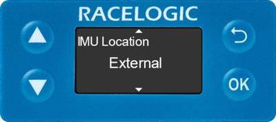
- Ensure IMU integration is 'Enabled', Location is set to 'External' and Roof mount is 'Disabled'.
- Enter the measured ahead/behind, right/left and above/below offset values within the 'Antenna to IMU offset' options.
Note: The options will be labelled 'Antenna to reference offset' if being used in conjunction with a Roof mount.
- Select 'Write to unit' to save the settings.
- Connect IMU04 to VBOX 3iS and then power the unit.
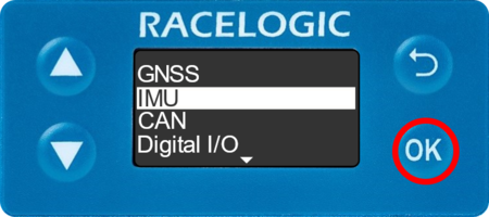
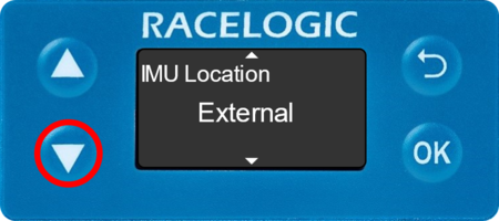
- Press the 'OK' button to enter the menu, navigate to 'IMU' using the 'Up' and 'Down' arrows and press the 'OK' button.
- Ensure IMU Integration is 'Enabled' and Location is set to 'External'.


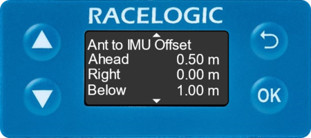
- Navigate to 'Ant to IMU Offset' using the 'Down' arrow, and press the 'OK' button to enter the menu.
Note: This menu is labelled 'Ant to Ref. Offset' if an External IMU is being used in conjunction with a Roof Mount.
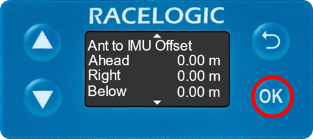


- Use a combination of the 'Up' and 'Down' arrows and the 'OK' button to enter the measured ahead/behind, right/left and above/below offset values.
Note: This menu is labelled 'The reference point is' when external IMU is being used in conjunction with a Roof Mount.

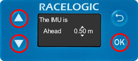
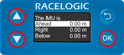
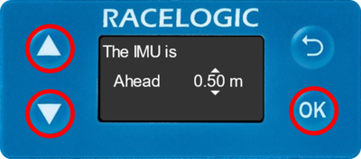
- Selecting the 'OK' button will move along digits and selecting past the final digit will store the value.
If IMU04 is placed on a non-flat surface, the 'Pitch/Roll Offset' action within the Front Panel of the VBOX 3iS unit or the VBOX Manager should be used to compensate the IMU attitude angle channels (pitch angle, roll angle).
This will zero the Pitch_imu and Roll_imu channels. Angle offsets calibration must be performed after the IMU Kalman Filter calibration has been completed, and the vehicle is static on a level surface.
- Press the 'OK' button on the front panel to enter the menu, navigate to 'IMU' using the 'Up' and 'Down' arrows and then press the 'OK' button.
- Ensure IMU Integration is 'Enabled' and Location is set to 'External'.
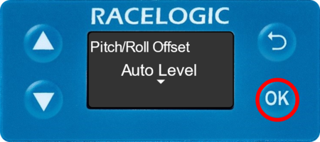
- Navigate to 'Pitch/Roll Offset' using the 'Down' arrow, and press the 'OK' button to enter the menu.


- Press the 'OK' button again to auto-level the pitch and roll offset.
Be aware that when mounting the IMU04 on an angle, the raw accelerometer and gyro data will be incorrect as the channels are not pitch compensated.