This page explains how to use a Racelogic DGPS Base Station to create a free NTRIP service that allow the connection of one or more test vehicles at the same time.
The Racelogic DGNSS RTK Base Station (RLVBBS4/5/6) has been used by customers for years to improve the positional accuracy of VBOX GNSS systems by calculating and then transmitting differential correction data via radio to allow a roving GNSS system to correct its position.
As customers test on roads outside their proving ground while still maintaining high positional accuracy, the need to transmit the corrections further than most radios allow has become a necessity.
Furthermore, on some test tracks it can be difficult to get reliable radio reception in all areas sometimes because of large elevation changes or where topographical obstacles can block a radio signal from the transmitting antenna.
The most common method to solve these issues has been to use Network RTK involving a communication link between the roving vehicle and a service provider.
Most network RTK systems are internet based and utilise a protocol called NTRIP (Networked Transport of RTCM via Internet Protocol). A constant internet connection is required to receive corrections, which can be done via a cellular modem, such as a VBOX NTRIP Modem, RLACS250 or a smart phone.
Using this type of correction requires registration and subscription to your local NTRIP provider as well as a cellular data plan. The annual fee for NTRIP subscriptions can be expensive or may not be available in some countries.
By using a Racelogic Base Station, a PC or laptop with an internet connection and an interface cable, it is possible to create an independent NTRIP service. The Base Station outputs correction messages to the PC or laptop via serial. The PC runs free software called SNIP, which then forwards the correction data to the RTK2go.com domain via an internet connection. The VBOX NTRIP Modem is then configured to connect to this domain and any number of VBOX 3i RTK, VBOX Touch RTK, VBOX Sigma, or any 3rd Party GNSS RTK Receivers can be used to receive the correction messages, to provide 2-cm positional accuracy of the test vehicle while in an area of good mobile/Wi-Fi and satellite coverage.
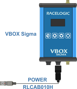
VBOX Sigma has a built-in NTRIP Modem, meaning it does not require the use of an additional cellular modem to connect to the NTRIP service.
The following steps are required to create the service and receive the correctional messages. These are discussed in more detail throughout this article.
- Connect the hardware
- Register the Base Station with RTK2go
- Configure the SNIP Software to send the data to RTK2go
- Enter the NTRIP Caster information within the NTRIP Modem
- Configure the RTK receiver(s) to receive the correction messages
Below is a list of the equipment necessary to create a simple NTRIP service.
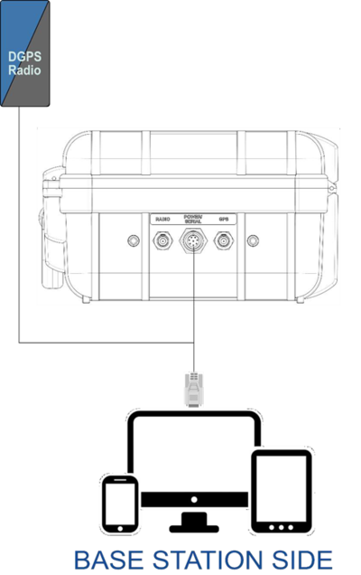
Base Station Side
1 x VBOX DGNSS Base Station RTK (RLVBBS4, RLVBBS5 or RLVBBS6)
1 x Custom Serial output cable
1 x PC or Tablet
1 x USB to Serial Adapter (RLACS076) if required
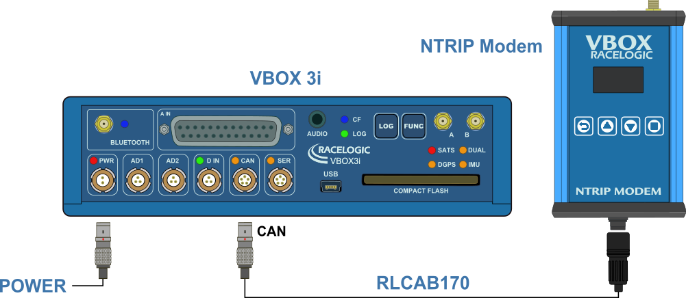
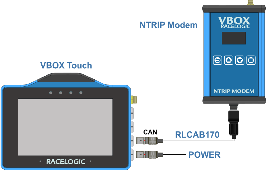
Roving Vehicle Side
1 x VBOX RTK Enabled Data Logger (RLVB4[X] / RLVB3iDR / RLVBTOUCHR / RLVBSIGMA)
1 x Racelogic NTRIP Modem (RLVBNTRIPMDM)
1 x NTRIP Modem Cable (RLCAB139)
1 x Activated SIM card with mobile data subscription (not required if using Wi-Fi connection)
NOTE
If the VBOX data logger is a VBOX Sigma, the Roving Vehicle Side does not require the NTRIP Modem and NTRIP Modem Cable.
Below are schematics showing the system installation and component connections.
An external mast-mounted DGPS radio is included to demonstrate that it can operate in parallel with the NTRIP service. The same setup applies if the DGPS radio is installed in the Base Station.
If the PC does not have a serial port, an RLACS076 USB-to-Serial Adapter is required.
If there is no Internet connection available at the Base Station, a DGPS radio can instead be connected to a PC that does have internet access, provided it is within radio range of the Base Station. In this setup, the DGPS radio connects to the PC via serial, allowing correction data to be transmitted over NTRIP.
Serial-to-Ethernet adapters can also be used to transmit serial data over a LAN; however, this configuration is outside the scope of this article.
The Base Station should be correctly set up and configured for outputting differential signals. Refer to the Base Station User Guide for more guidance if necessary.
Before you can send the correctional data to the RTK2go.com domain, you must register the Base Station with name, email and Mount Pt name information.
Every data stream has its own entry within the caster table, which allows each user to see what the caster offers and select the best data stream for their needs.
The new data stream must have a locally unique Mount Pt name to differentiate it from other streams. The name must be a single word and must not contain certain characters.
Refer to the RTK2go website for more information.
Once the Base Station has been registered, the system will send you an email with the password for connecting to the caster in the SNIP Software.
There are 2 steps required to configure the SNIP software:
- Set the PC COM port to receive the serial data stream from the base station.
- Configure the internet destination of this stream to RTK2go.com.
The following steps will guide you through the configuration of the SNIP software:
- Download SNIP and install the software.
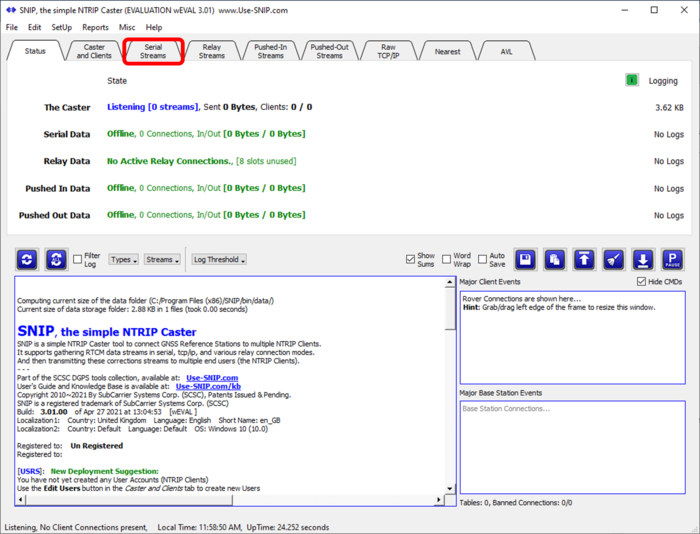
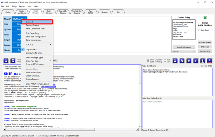
- Open the SNIP software and click on the Serial Streams tab.
IMPORTANT
Make sure that the Base Station is plugged in and that there are suitable working device drivers installed for your operating system before you move to the next step.
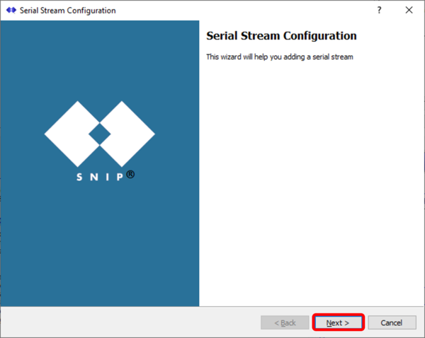
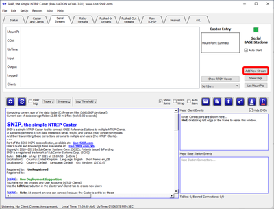
- Click the Add New Stream button to start the configuration.
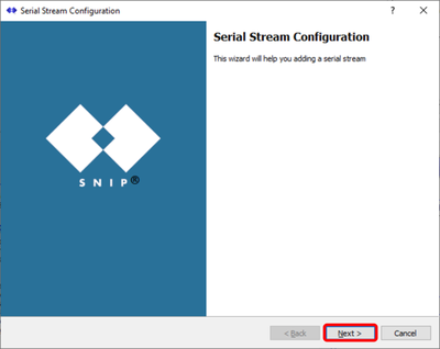
- Click the Next in the popup window.

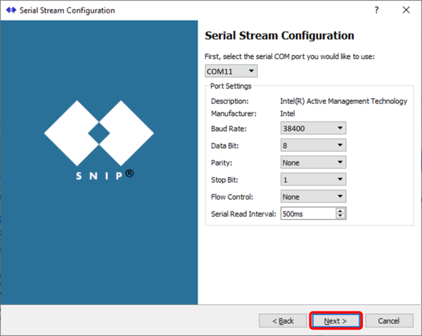
- Make sure that the baud rate setting in the Serial Stream Configuration window matches the baud rate of the Base Station.
In the example below, the USB to serial adapter is connected to COM11 and the baud rate is 38400 which matches the Base Station baud rate. - Click 'Next'.
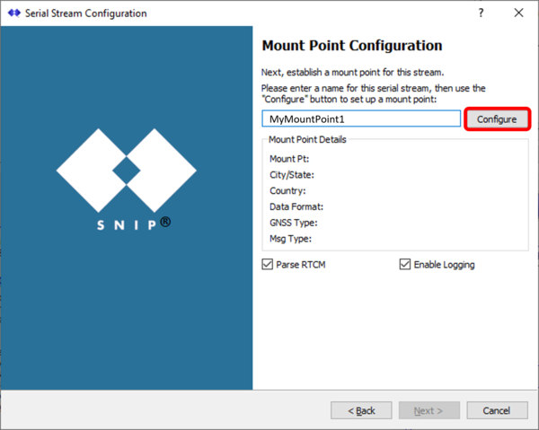
- Enter the Mount Pt name used to register the Base Station and click the Configure button.
The software will check the entry to make sure that it is unique and will provide various corrective hints for the different data entries when needed.
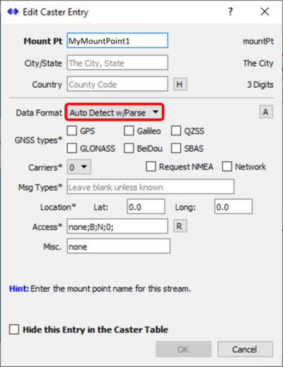
- Select the data format Auto Detect w/Parse.
In this mode, SNIP will perform an initial analysis of the data stream when it first starts and then correctly fill in the Caster Table entry for you, including the types and rates of the messages, the gross location of the Base Station, the GNSS types (GPS, GLONASS, etc.), signal types (L1/L2/L5) and other details. - Click OK.
NOTE
Leave the Hide this Entry in the Caster Table option unticked.
- Click Next in the Start-up/Shut-down Command Configuration window to skip this step as it is not required for this configuration.
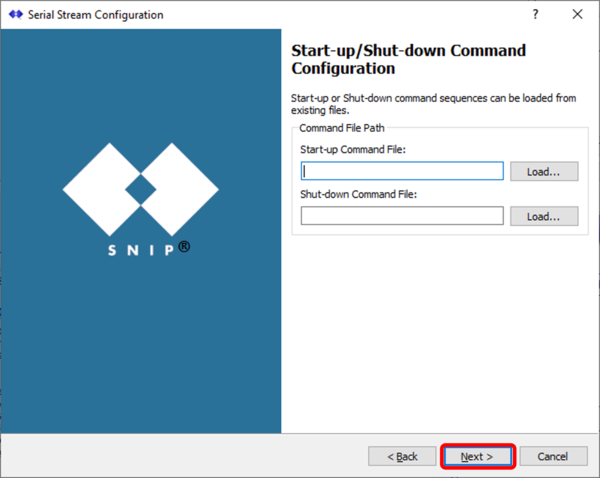
- Click Finish to complete the configuration.
- Right-click on the MountPt name and click Connect.
Once any setup data about a port has been entered, it is retained and will be used when SNIP next opens. If you have enabled the Auto Start checkbox, all your serial streams will automatically restart without further intervention.
After 30 seconds of operation, the details of the caster table entry are shown in the label on the right. The white area to the right of the slot summary is where any additional serial streams would be displayed. The green colour indicates a current state of error-free operation.
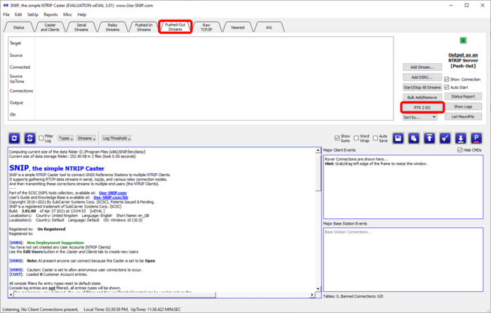
- Click on the Pushed-Out Streams to open it and click the RTK 2 GO button to start the configuration.
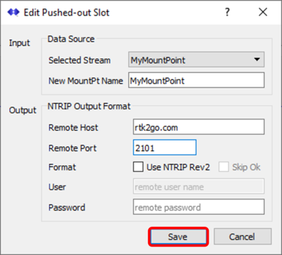
- Select the Serial Stream that has just been configured from the Selected Stream drop-down list.
- Enter the password emailed to you by RTK2go.
- Input the Remote Host as "rtk2go.com" and the Remote Port as "2101".
- Click Save.
SNIP will now send the serial data to the RTK2go.com domain.
The modem screen will display a Wi-Fi hotspot name and IP address which is used for configuration of the unit.
- Using a mobile phone or a Wi-Fi capable computer, navigate to the Wi-Fi settings on the device and connect to the hotspot name (RL-4C11AEDBDCE9 in the example below).
- Open an internet browser and enter the IP address (192.168.1.1 in the example below) within the address bar.
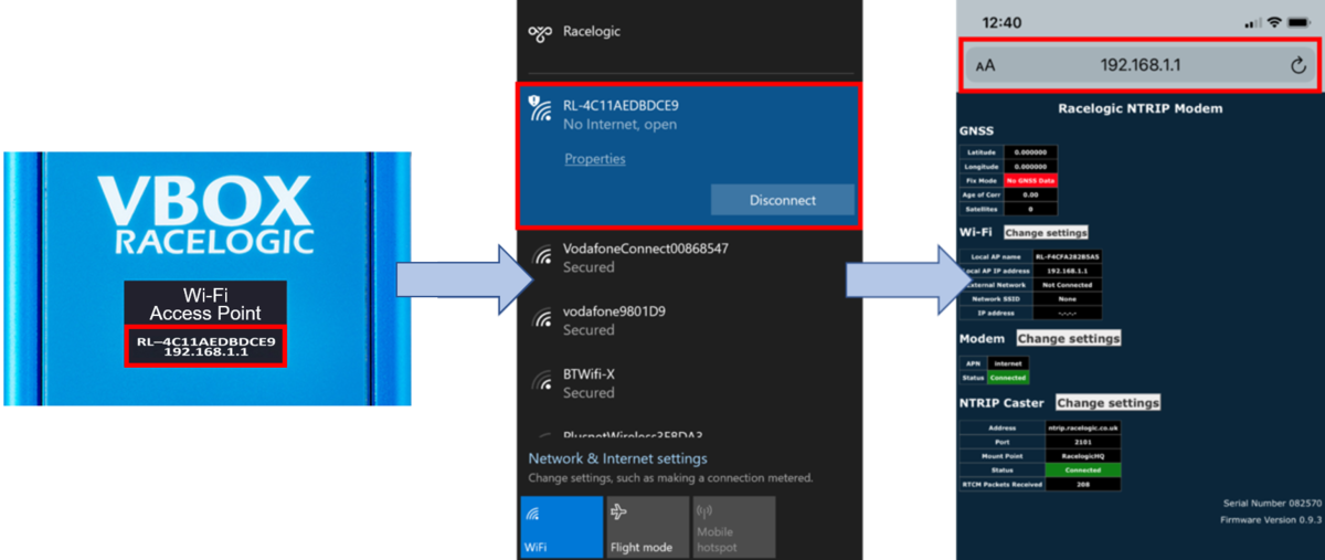
The NTRIP Modem setup page is then displayed, which includes Wi-Fi, modem and NTRIP caster settings and status information, along with the connected GNSS engine status. The serial number and firmware version of the unit is displayed on the bottom right of the page.
Refer to the NTRIP Modem User Guide for more information about the NTRIP Modem Web Interface and how to configure the modem.
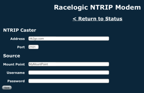
The NTRIP Caster area of the Web Interface displays NTRIP correction service connection information.
- Configure the NTRIP correction service details by clicking on the Change settings button next to the NTRIP Caster heading and entering the following NTRIP Caster information:
NTRIP Caster Address: rtk2go.com
NTRIP Caster Port: 2101
Source Mount Point: ******** (registered mount point name)
Source User Name: Not required
Source Password: Not required
The NTRIP modem will attempt to connect to the NTRIP server using the provided details.
Once connected to the NTRIP server, the unit will briefly display an RTCM Streaming message.
If there is a problem with the server details, the unit will display an Invalid Caster Credentials message.
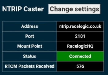
The settings page will be updated with the new settings and provide a connection status indication along with the number of data bytes received from the NTRIP server. The display on the NTRIP Modem will also provide this information.
If connected to a VBOX 4 / VBOX 3i, the DIFF LED on the VBOX should illuminate in solid green after about 5 seconds, indicating that it is receiving DGPS corrections.
As VBOX Sigma has an integrated NTRIP Modem, it does not require the use of an additional cellular modem to connect to the NTRIP service. Configuration is performed using a Wi-Fi hotspot created by the unit. The hotspot name and IP address is displayed on the Network Screen on the unit display when it is powered. Use the arrow buttons on the front of the unit to navigate to it.
- Using a phone or a computer, navigate to the Wi-Fi settings on the device and connect to the hotspot name (RL-212101 in the example below). Open an internet browser and enter the IP address (10.10.10.1 in the example below) within the address bar.
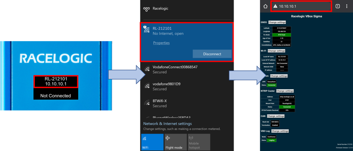
The VBOX Sigma setup page is then displayed, which includes the GNSS engine status, Wi-Fi, modem, NTRIP caster settings, CAN, VBO log and status information.
The serial number and firmware version of the unit is displayed on the bottom right of the page.
Refer to the VBOX Sigma User Guide for more information about the Web Interface and how to configure the unit.
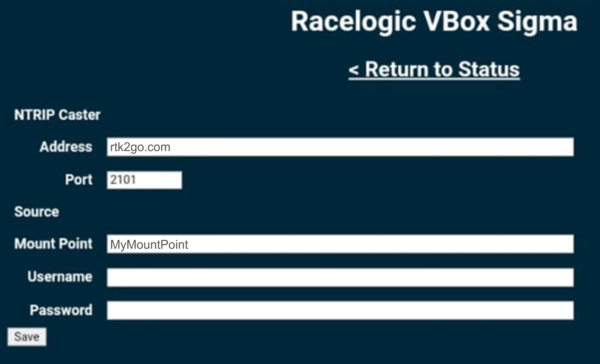
The NTRIP Caster area of the setup page displays NTRIP correction service connection information.
2. Configure the NTRIP correction service details, press the Change settings button next to the NTRIP Caster heading and enter the NTRIP Caster Settings as follows:
NTRIP Caster Address: rtk2go.com
NTRIP Caster Port: 2101
Source Mount Point: ******** (registered mount point name)
Source User Name: Not required
Source Password: Not required
VBOX Sigma will then attempt to connect to the NTRIP server using the provided details. Once connected to the NTRIP server, the unit will briefly display an 'RTCM Streaming' message. If there is a problem with the server details entered, the unit will briefly display an 'Invalid Caster Credentials' message.
The settings page will be updated with the new settings and provide a connection status indication along with the number of data bytes received from the NTRIP server. The Home Display Screen will also provide this information.
VBOX 3i RTK must have the correct DGPS mode enabled in VBOX Setup or VBOX Manager before it is capable of receiving and using the DGPS correction information transmitted by the Network RTK Service Provider.
- Run the latest VBOX Setup software.
- Go to the 'GPS' page.
- Under the DGPS / RTK section, select 'NTRIP' from the available options.
- Select '115200' in the available options for the RS232 baud rate.
- Select 'Write to unit'.
- Connect VBOX Manager.
- Enter 'SETUP' menu and go to 'VBOX'.
- Enter 'DGPS Mode' and select 'NTRIP' from the available options.
- Select 'Back'.
- Enter 'DGPS Rate' and select '115200'.
- Exit out of the Setup Menu.
VBOX Touch RTK must have the NTRIP Mode enabled before it can receive and use the DGNSS correction information transmitted by the Network RTK Service Provider.
- Apply power to the unit and then go to the Settings menu by selecting the Settings button on the bottom left of the screen.
- Tap the Serial Port settings button.
- Under RTK Input, enable NTRIP Mode and make sure that the DGPS Baud Rate is 115200.
NOTE
You can also change the 3rd tracked constellation (Beidou or Glonass) in the GNSS Selection on the General Settings screen.
If you are intending to use 3rd Party GNSS RTK Receivers rather than a Racelogic solution, you will need to ensure that any available 'NTRIP' option is selected and that '115200 kbit/s' is chosen as the RS232 baud rate.