In the Tests menu in VBOX Setup, connected to a VBOX 3iS unit, you can configure brake test and lap timing settings.
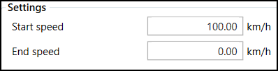
Configure the start and end speed of non-trigger deceleration tests.
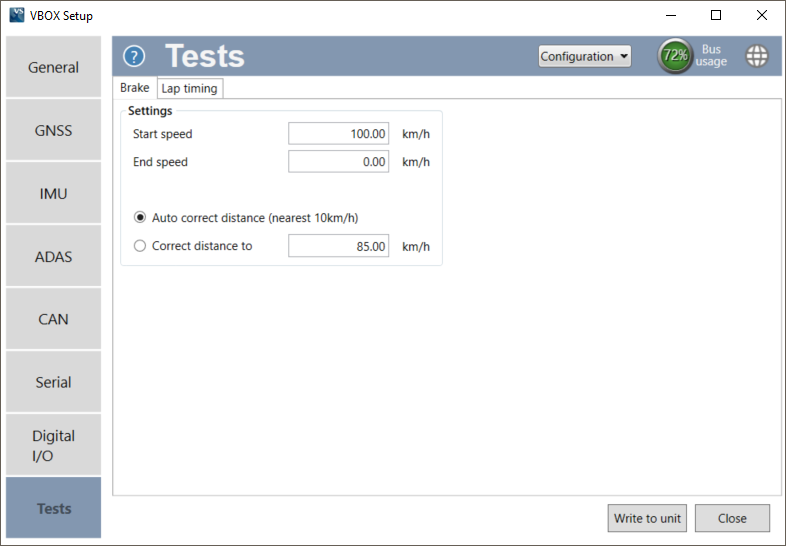
Defines the start/end speed at which the test will begin and finish, set as 100 km/h and 0 km/h by default.
Defines the start/end speed at which the test will begin and finish, set as 100 km/h and 0 km/h by default.

This sets the speed sensor to use the nearest rounded 10 km/h speed when the trigger is activated. For example, if the trigger speed was 104 km/h, then 100 km/h would be the nominated start speed for the corrected brake stop distance.

This sets the speed sensor to use the nearest rounded 10 km/h speed when the trigger is activated. For example, if the trigger speed was 104 km/h, then 100 km/h would be the nominated start speed for the corrected brake stop distance.
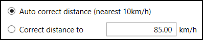
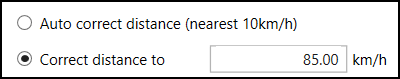
If the Auto option is not selected, you can specify a speed value to correct all deceleration tests to.
If the Auto option is not selected, you can specify a speed value to correct all deceleration tests to.

Configure the lap timing settings, start/finish and split gates.
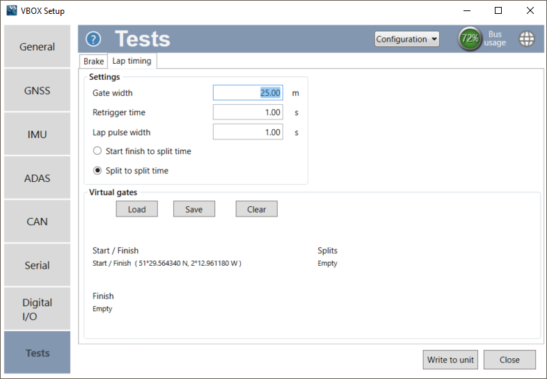
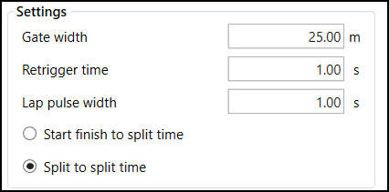
This sets the width of any gates set (25 m by default). It is a useful feature when two parts of a track run very close to each other, or the pit lane is next to the start/finish line, as lowering this value can stop the virtual line being triggered by the incorrect area of the circuit.
This allows the user to set a number of seconds during which the brake trigger will not be reactive after having been pressed (1 s by default). This is to avoid trigger bounce during tests.
This option controls the duration of the lap time and splits the CAN pulse (1 s by default). Other lap timing CAN channels such as Lap Marker, start/finish crossing pulse or gate crossing pulse marker set to 2 s duration as default, or the highest analogue or digital pulse duration setting if greater. The CAN pulse width can not exceed any Digital or Analogue Lap pulse output duration. If an invalid setting is set, the software will not allow writing to the unit. Hovering over the Write to unit button will report an invalid setting.
Note: For a Lap Beacon Pulse to be output by VBOX 3iS, you must make sure that it has loaded valid virtual gate(s) have been loaded.
Determines whether the 'Split Time' CAN channel is either the total lap time at split cross or the delta time between split lines.
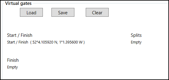
Use the Load button to load a .spl, .dsf or .vbo file containing start/finish and split gates. The gates can also be saved in a different format by selecting the Save button or removed using the Clear button.