There are different instructions for setting up and installing your system depending on your system. You can see the instructions for your system by clicking on the relevant VBOX unit below.
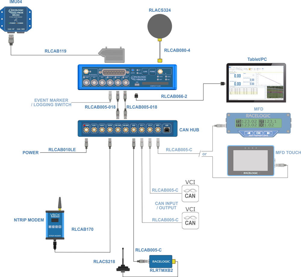
- Connect one end of an RLVBCAB005-018 to the VB CAN port on the CAN Hub unit.
- Connect the other end of the cable to the CAN port on the VBOX 3i Single Antenna unit.
- Connect one end of a second RLVBCAB005-18 to the VB SER port on the CAN Hub unit.
- Connect the other end of the second cable to the SER port on the VBOX 3i Single Antenna unit.
- You can power the VBOX 3i and CAN Hub units via the PWR port on the CAN Hub unit. Use either the mains adaptor or a fully charged battery pack.
NOTES
- You must set the CAN profile on the VBOX 3i unit to default (Racelogic CAN on the CAN port).
- If you are using a VBOX Manager with the CAN Hub, the VBOX Manager unit must be running v2.55 b2844 or later and must only be connected to the MFD port!
- If you are using an MFD with the CAN Hub, the MFD unit must be running v13.05 or later and the baud rate must be set to 1 MB/s.
- If you are using an ADC03 unit or a TC8 unit, you must isolate them on their own using either the CAN1 port or the CAN2 port.
- The CAN1 and CAN2 ports are isolated.
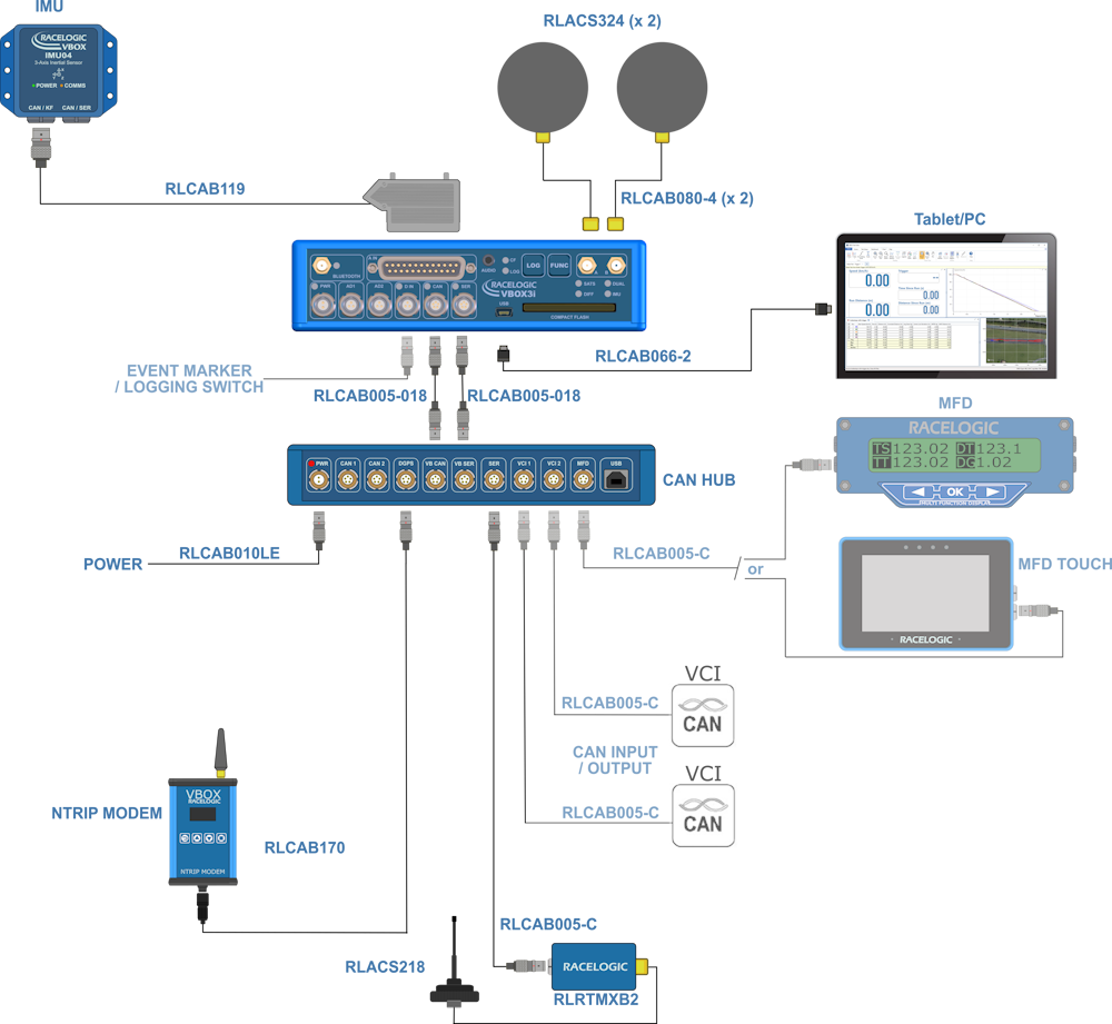
- Connect one end of an RLVBCAB005-018 to the VB CAN port on the CAN Hub unit.
- Connect the other end of the cable to the CAN port on the VBOX 3i Dual Antenna unit.
- Connect one end of a second RLVBCAB005-18 to the VB SER port on the CAN Hub unit.
- Connect the other end of the second cable to the SER port on the VBOX 3i Dual Antenna unit.
- You can power the VBOX 3i and CAN Hub units via the PWR port on the CAN Hub unit. Use either the mains adaptor or a fully charged battery pack.
You can find more specific information about the ports on the CAN Hub in Inputs and Outputs - CAN Hub.
NOTES
- You must set the CAN profile on the VBOX 3i unit to default (Racelogic CAN on the CAN port).
- If you are using a VBOX Manager with the CAN Hub, the VBOX Manager unit must be running v2.55 b2844 or later and must only be connected to the MFD port!
- If you are using an MFD with the CAN Hub, the MFD unit must be running v13.05 or later and the baud rate must be set to 1 MB/s.
- If you are using an ADC03 unit or a TC8 unit, you must isolate them on their own using either the CAN1 port or the CAN2 port.
- The CAN1 and CAN2 ports are isolated.

- Connect one end of an RLVBCAB005-018 to the VB CAN port on the CAN Hub unit.
- Connect the other end of the cable to the CAN port on the VBOX 3i RTK unit.
- Connect one end of a second RLVBCAB005-18 to the VB SER port on the CAN Hub unit.
- Connect the other end of the second cable to the SER port on the VBOX 3i RTK unit.
- You can power the VBOX 3i and CAN Hub units via the PWR port on the CAN Hub unit. Use either the mains adaptor or a fully charged battery pack.
You can find more specific information about the ports on the CAN Hub in Inputs and Outputs - CAN Hub.
NOTES
- You must set the CAN profile on the VBOX 3i unit to default (Racelogic CAN on the CAN port).
- If you are using a VBOX Manager with the CAN Hub, the VBOX Manager unit must be running v2.55 b2844 or later and must only be connected to the MFD port!
- If you are using an MFD with the CAN Hub, the MFD unit must be running v13.05 or later and the baud rate must be set to 1 MB/s.
- If you are using an ADC03 unit or a TC8 unit, you must isolate them on their own using either the CAN1 port or the CAN2 port.
- The CAN1 and CAN2 ports are isolated.
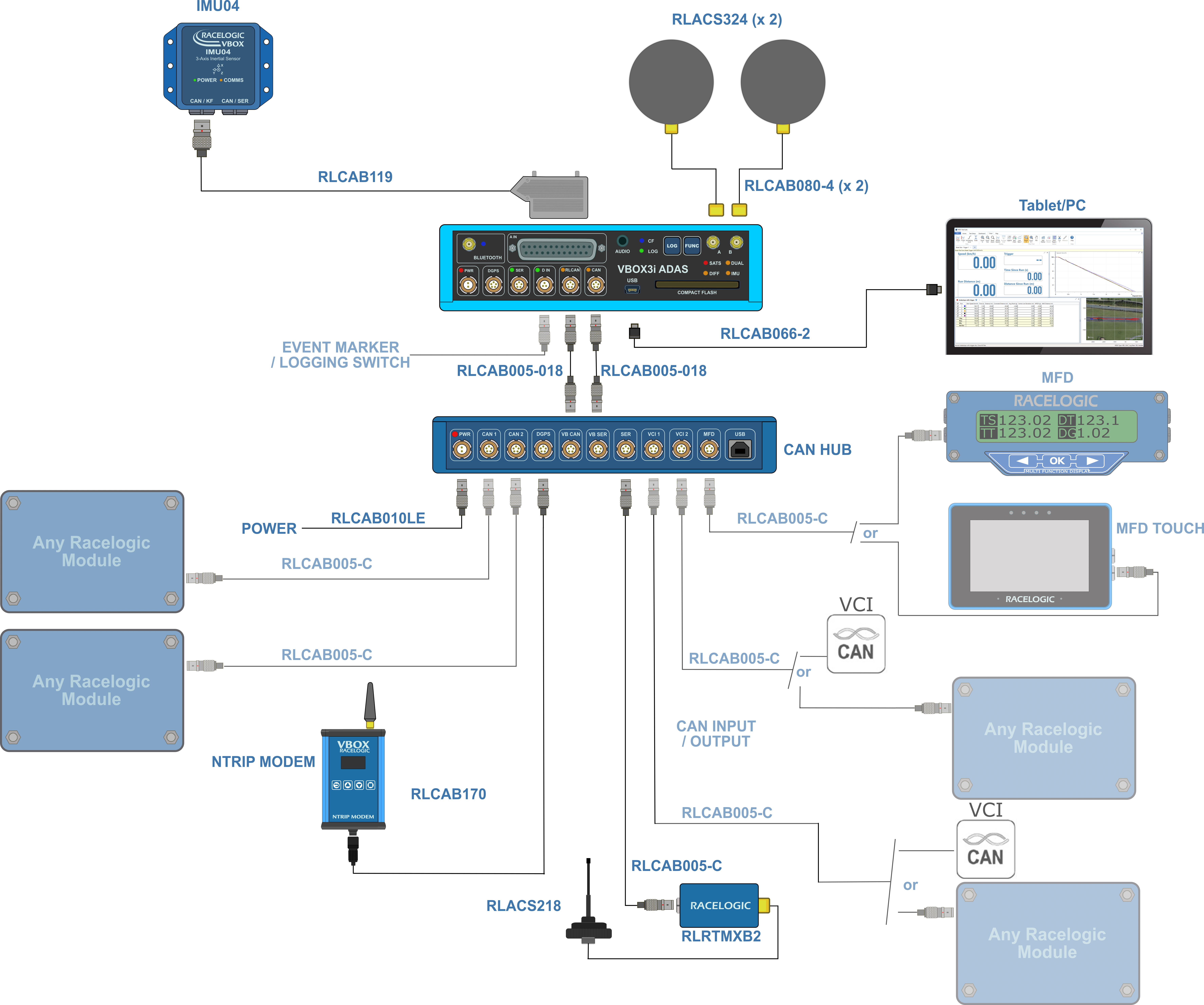
- Connect one end of an RLVBCAB005-018 to the VB CAN port on the CAN Hub.
- Connect the other end of the cable to the RL CAN port on the VBOX 3i ADAS.
- Connect one end of a second RLVBCAB005-18 to the VB SER port.
- Connect the other end of the second cable to the CAN port on the VBOX 3i ADAS.
- You can power the VBOX 3i and CAN Hub units via the PWR port on the CAN Hub unit. Use either the mains adaptor or a fully charged battery pack.
You can find more specific information about the ports on the CAN Hub in Inputs and Outputs - CAN Hub.