NOTE
These notes are specifically for OLED use with VBOX Video HD2. The full OLED manual can be accessed here.
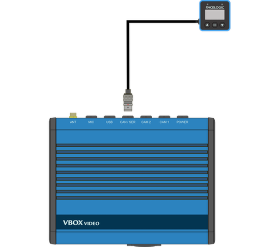
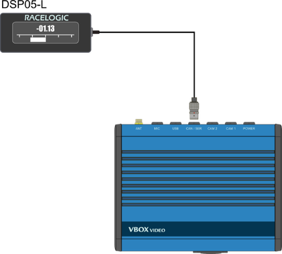
As the OLED display uses a serial connection to display information from the VBOX Video HD2, the CAN / SER port on the HD2 must be used.


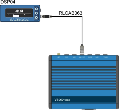

- DSP04 Blue OLED display: Connect an RLCAB063 cable from the lower connector (with the buttons on the right hand side) on the OLED to the CAN / SER port on the HD2. The configuration is indicated on a label on the rear of the OLED display.
- DSP05 Black OLED display: Connect the flying lead on the OLED to the CAN / SER port on the HD2.
- DSP06 Mini OLED display: Connect the flying lead on the OLED to the CAN / SER port on the HD2.
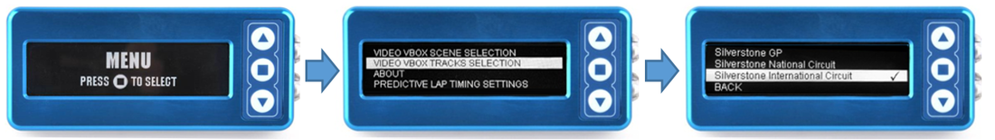
This feature allows the HD2 to search through a built in circuit database of over 500 circuits and load all layouts from the detected GPS location.
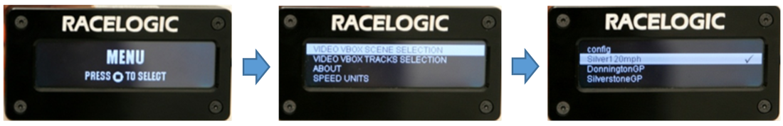
Using an OLED display, a specific layout can be selected when at a location with multiple circuits. After arriving at a circuit and allowing the HD2 to gain a GPS lock, the desired circuit layout can be selected, as shown below.
When a track is chosen, the start/finish line will be automatically synchronised.
The VBOX Video HD2 can store up to eight user defined scenes. They are loaded by placing all files in the root directory of logging media (SD Card or USB stick) and inserting them into the HD2 unit when it is powered on. The HD2 will load all scenes from the media device and save them to its internal memory. More information on loading scenes is available here.
The user can select the scene using an OLED display as shown below.
NOTES
- If the user tries to load more than eight scenes, the HD2 will reject all the scene files and write an error message to the SD card.
- Scene selections cannot be added to with single scene files. The whole group of scenes must be loaded at a single time.
- If more than 1 scene file is loaded and you don't have access to a display, the first scene alphabetically will be used by the unit.
- The scene file(s) will be removed from the memory storage when installed to the unit.
By default, VBOX Video HD2 is set up to work with the OLED display. There is a serial application setting within General Settings (Windows, macOS) which can be set to ‘none’, which will stop all data being sent to the OLED and cause a ‘communication error’ to be displayed on the OLED screen.
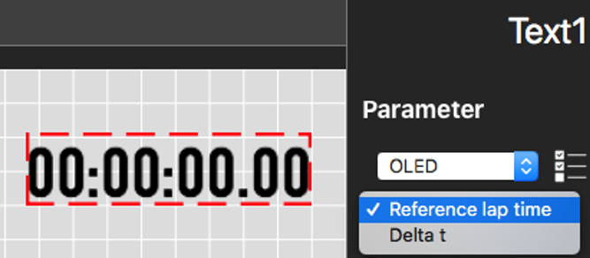
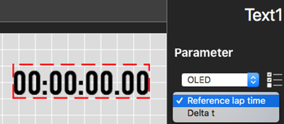
It is possible to add OLED parameters as text items within the scene using the VBOX Video Setup software (Windows, macOS).
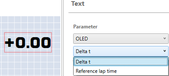

- Delta t: Presents a live difference in lap time between the current lap time and the stored and active reference lap at the current location on track.
IMPORTANT
This parameter will only update within the scene if the Predictive Lap Timing screen is being displayed on the OLED.
- Reference lap time: Displays the current active reference lap time, which will update when the reference lap is superseded by a faster lap-time, unless the Reference Lap is Fixed.