- Make sure that you have VBOX Audio Sensor Setup installed on your PC.
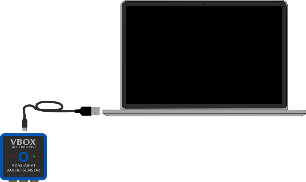
- Connect your ADAS Audio Sensor to your PC with a USB-A to USB-C cable.
NOTE
This cable will power the unit and provide access to configure the detection and trigger settings.
- Make sure that you have VBOX Audio Sensor Setup installed on your PC.
- Connect your ADAS Audio Sensor to your PC with a USB-A to USB-C cable.
NOTE
This cable will power the unit and provide access to configure the detection and trigger settings.
- Open VBOX Audio Sensor Setup.
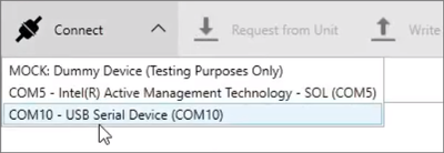
- Click on the Connect button to open the dropdown list of available COM ports and select the port that you connected the Audio Sensor to. (It will be labelled as USB serial device.)

- Open VBOX Audio Sensor Setup.
- Click on the Connect button to open the dropdown list of available COM ports and select the port that you connected the Audio Sensor to. (It will be labelled as USB serial device.)
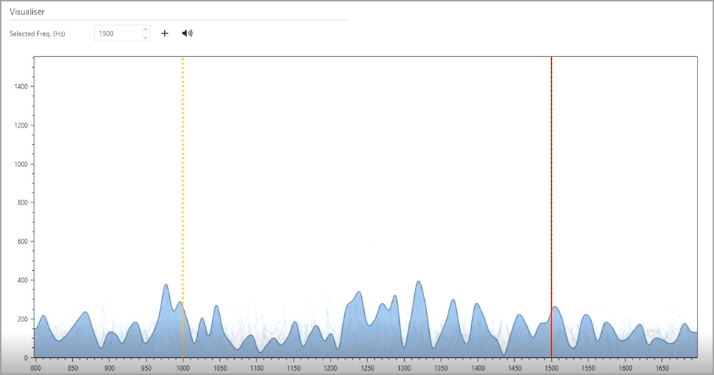
- When the software has connected to the unit, the graph in the Visualiser will automatically populate and show live feedback of background noise captured by the Audio Sensor's internal microphone (or external microphone if used).
- When the software has connected to the unit, the graph in the Visualiser will automatically populate and show live feedback of background noise captured by the Audio Sensor's internal microphone (or external microphone if used).

- Select the frequency you wish to detect.
You can do this by either clicking directly on the graph to select that frequency, typing the frequency directly into the Selected Freq. (Hz) value box, or using the arrow buttons next to the Selected Freq. (Hz) value box to increase or decrease the frequency value. - You can replay the selected frequency in the software to confirm your selection by clicking on the speaker icon next to the selected frequency in the Visualiser.
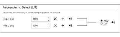
- Click on the + icon next to the Selected Freq. to add the currently selected frequency to the Frequencies to Detect list.
You can add a maximum of 4 frequencies to detect.
- You can set the unit to trigger using the AND or OR functionalities:
AND
When you select AND, the signal detection will only be triggered when all of the frequencies are met simultaneously. You can use this for multi-toned warnings or multi-vibration haptic warnings.
Using AND triggering will significantly reduce false positives from any background noise.

AND
When you select AND, the signal detection will only be triggered when all of the frequencies are met simultaneously. You can use this for multi-toned warnings or multi-vibration haptic warnings.
Using AND triggering will significantly reduce false positives from any background noise.
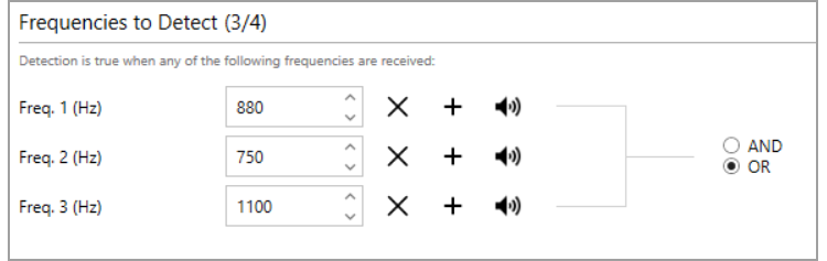
OR
When you select OR, the sensor output will be activated when the unit detects any of the configured frequencies. The Audio Sensor’s CAN bus output contains individual data bits for each frequency. This makes it possible for a connected VBOX 3i unit to establish and highlight which vehicle warning sound has been detected. For example, if it is a seat belt reminder or a Forward Collision Warning.
Additionally, it is common for warnings to rise in both frequency and intensity the longer they have to sound. (Such as the seat belt reminder or the warning cascade described in UNECE R79). The multiple frequency option with OR triggers will give you the ability to measure individual timings in the escalation of warning sounds.
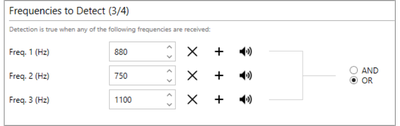
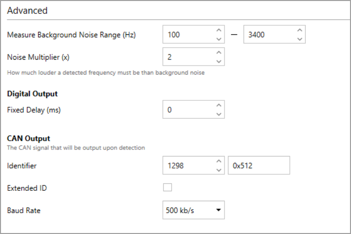
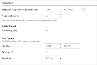
- Go to the Advanced Settings area to adjust the following settings, if applicable:
Measure Background Noise Range
Noise Multiplier
Digital Output Fixed Delay (ms)
CAN Output
- Go to the Advanced Settings area to adjust the following settings, if applicable:
Measure Background Noise Range
Noise Multiplier
Digital Output Fixed Delay (ms)
CAN Output
- When you are happy with the configured settings, click Write to Unit to save the configuration to your Audio Sensor unit.

- When you are happy with the configured settings, click Write to Unit to save the configuration to your Audio Sensor unit.