
IMPORTANT
Due to the improved accuracy when connecting via Analogue Input and applying a compensated delay, we recommend that you always connect the Audio Sensor to the VBOX as an Analogue Input for high-accuracy applications.
The compensated delay must be configured for both the Audio Sensor and the test plugin in VBOX Test Suite. For more information on applying a compensated delay to the Audio Sensor signal itself, see the VBOX Audio Sensor Setup Overview. For more information about applying a compensated delay in the form of a Fixed Audio Delay in the test plugin settings, see the relevant Test Suite Plugin Configuration Guide.
Audio sensor powered via VBOX 4 ADAS - Analogue Input Connector
After wiring the unterminated end of RLCAB007-2 to the 15-way D-sub connector as illustrated below, you can connect the 15-way D-sub connector to the ANALOGUE INPUTS port on the VBOX 4 ADAS unit and the Lemo connector to the TRIG OUT port on the Audio Sensor.

| Wire Colour | Function |
|---|---|
| Red | Power |
| Green | Ground |
| Yellow | Signal Ground |
| Blue | Signal |

| Wire Colour | Function |
|---|---|
| Red | Power |
| Green | Ground |
| Yellow | Signal Ground |
| Blue | Signal |
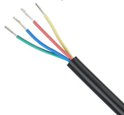
- Wire the green wire to the ground pin (15).
- Wire the red wire to the power pin (9).
- Wire the yellow wire to a negative pin in an available Isolated Channel pair.
- Wire the blue wire to a positive pin in an available Isolated Channel pair.
In this example, we are using channel 4 for the signal wires.
You can find the pin information for the Analogue Input connector on VBOX 4 ADAS here.

Note: Take note of the channel you are connecting the signal wires to, as you will need to configure this channel in the Channel Setup menu in the VBOX Setup software when you connect the sensor to the VBOX.
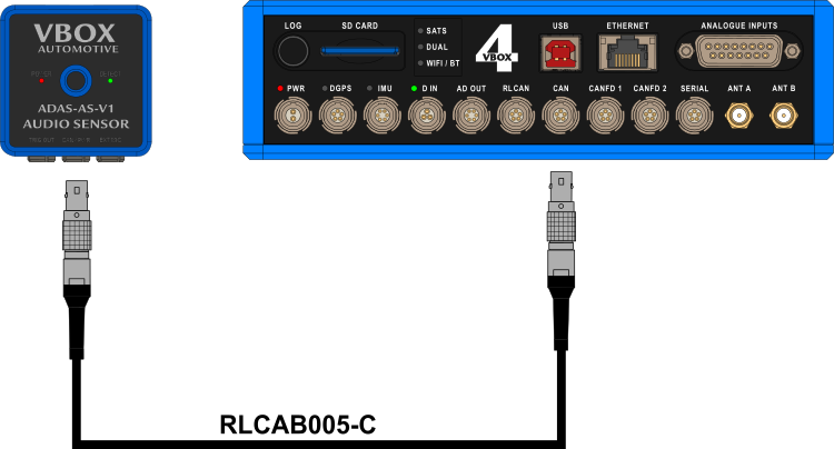
Audio sensor powered via VBOX 4 ADAS - CAN Connector
You can connect the ADAS Audio Sensor to VBOX 4 ADAS units with the RLCAB005-C CAN cable.
Connect one Lemo connector to the CAN port on the VBOX 4 ADAS unit and the other connector to the CAN/PWR port on the Audio Sensor.
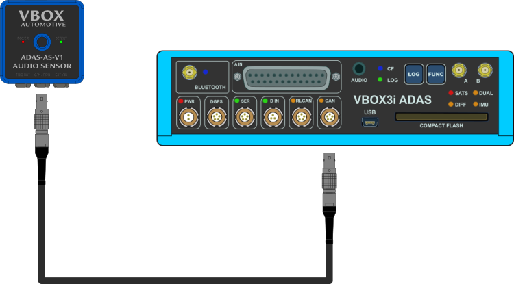
Audio sensor powered via VBOX 3i - Analogue Input Connector
After wiring the unterminated end of RLCAB007-2 to the 25-way D-sub connector as illustrated below, you can connect the 25-way D-sub connector to the A IN port on the VBOX 3i unit and the Lemo connector to the TRIG OUT port on the Audio Sensor.

| Wire Colour | Function |
|---|---|
| Red | Power |
| Green | Ground |
| Yellow | Signal Ground |
| Blue | Signal |
| Wire Colour | Function |
|---|---|
| Red | Power |
| Green | Ground |
| Yellow | Signal Ground |
| Blue | Signal |
- Wire the green wire to the ground pin (15).
- Wire the red wire to the power pin (14).
- Wire the yellow wire to a negative pin in an available Isolated Channel pair.
- Wire the blue wire to a positive pin in an available Isolated Channel pair.
In this example, we are using channel 1 for the signal wires.
You can find the pin information for the analogue Input connector on VBOX 3i here.

Note: Take note of the channel you are connecting the signal wires to, as you will need to configure this channel in the Channel Setup menu in the VBOX Setup software when you connect the sensor to the VBOX.
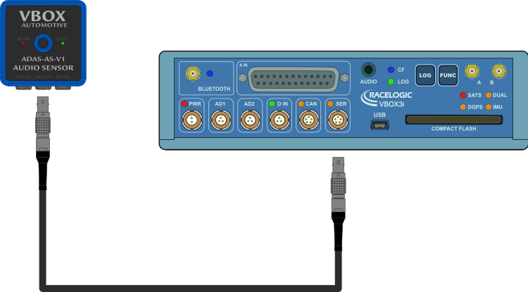
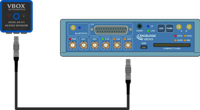
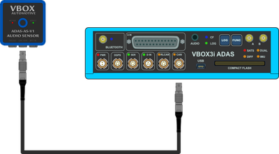
Audio sensor powered via VBOX 3i - CAN Connector
You can connect the ADAS Audio Sensor to VBOX 3i units with the RLCAB005-C CAN cable.
VBOX 3i RTK: Connect one Lemo connector to the SER port (when using default CAN/SER settings) on the VBOX 3i unit and the other connector to the CAN/PWR port on the Audio Sensor.
VBOX 3i ADAS: Connect one Lemo connector to the CAN port on the VBOX 3i ADAS unit and the other connector to the CAN/PWR port on the Audio Sensor.
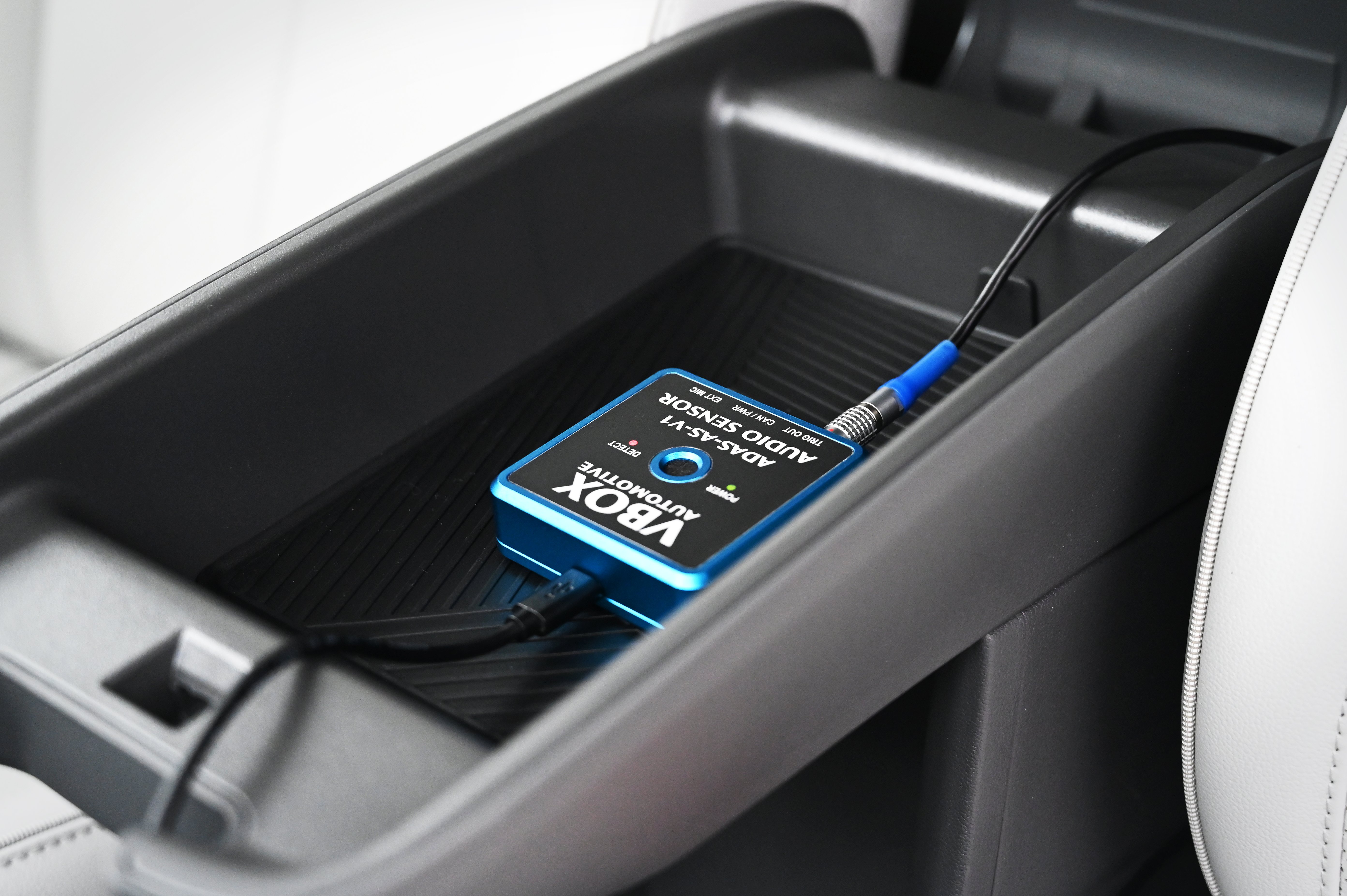
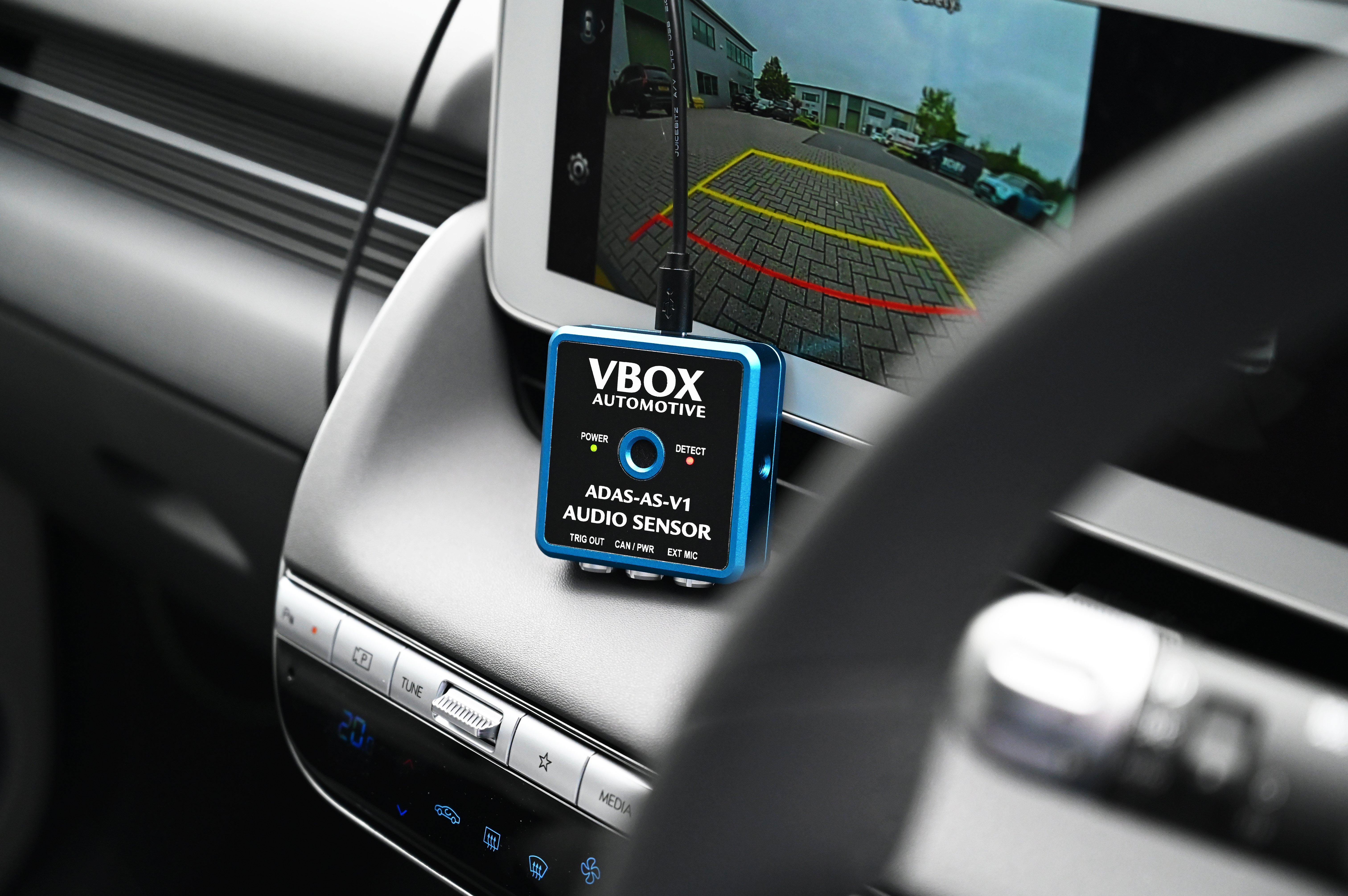
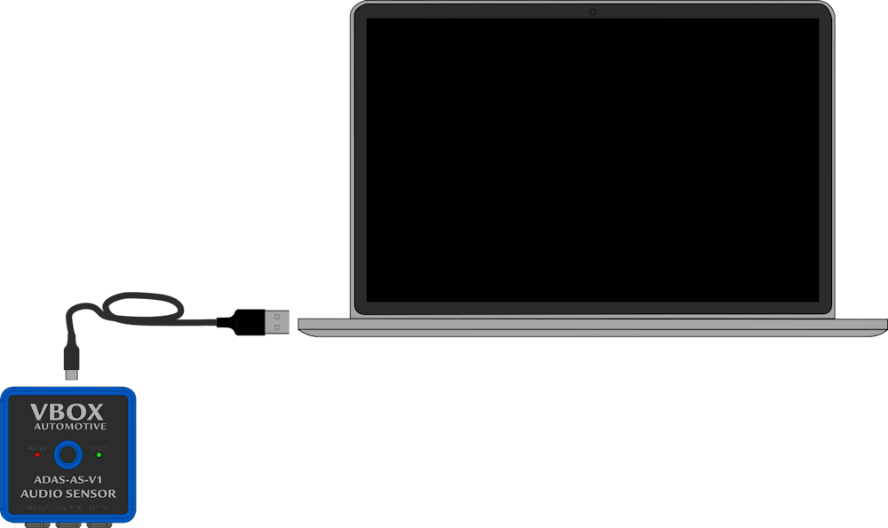
You can connect the Audio Sensor to the PC to use the VBOX Audio Sensor Setup software to configure and preview the audio sensor.
Connect the TV1AM20MB31 cable (USB cable) to the USB-C port on the back of the Audio Sensor and the USB-A port on the PC.
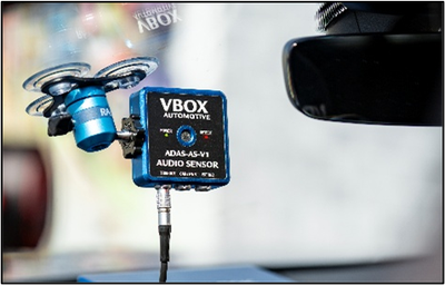
If you need to use the extrernal microphone with your Audio Sensor to capture sounds from hard-to-reach locations, you can easily connect the Lemo connector on the microphone to the EXT MIC port on the Audio Sensor.
Note: Please make sure that the unit is power cycled after the external microphone is connected or disconnected.