In the IMU menu in VBOX Setup, connected to a VBOX 3iS unit, you can configure the IMU location, offset position and orientation, as well as the wheel speed inputs.
Configure the IMU integration, location, and offset position.
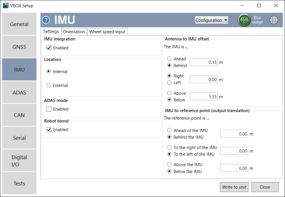
This option turns on IMU integration. When enabled, the other IMU options are presented and the Wheel speed input tab appears.

This option turns on IMU integration. When enabled, the other IMU options are presented and the Wheel speed input tab appears.
Specifies whether the speed sensor will be using its in-built IMU or an external IMU.
Specifies whether the speed sensor will be using its in-built IMU or an external IMU.

Disable the ADAS mode when you want better speed or attitude performance testing, such as in Brake Stop tests.
Enable the ADAS mode when you need a highly accurate position.

Disable the ADAS mode when you want better speed or attitude performance testing, such as in Brake Stop tests.
Enable the ADAS mode when you need a highly accurate position.
Enabling the Robot Blend mode will stop the unit from making large positional jumps by stopping the Kalman Filter from correcting itself by more than 1 mm per sample when the GPS is trustworthy.
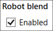
Enabling the Robot Blend mode will stop the unit from making large positional jumps by stopping the Kalman Filter from correcting itself by more than 1 mm per sample when the GPS is trustworthy.

Note: The Roof Mount option is only presented when the IMU Location is set to External.
This setting specifies whether you are using a roof-mounted IMU from Racelogic or not. You should enable this when you have an external IMU installed on the roof mount that the primary antenna is mounted on.
When it is Enabled, it will automatically configure an Antenna to IMU offset to account for the 3 cm distance between the IMU and Antenna on the Roof Mount and the Ant to IMU Offset setting will become Ant to Ref. Offset.

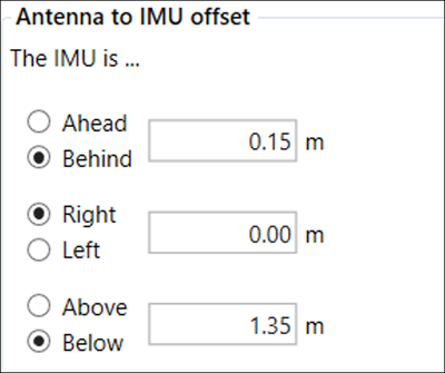
This is where you can add offset values to let the VBOX unit know where the antenna is positioned relative to its own position.
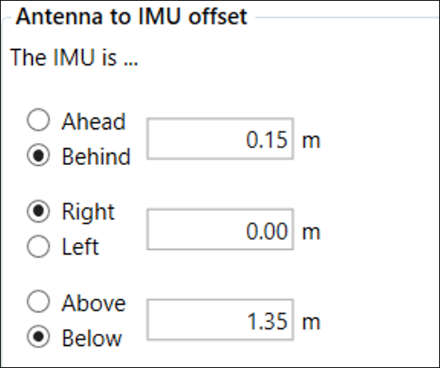
This is where you can add offset values to let the VBOX unit know where the antenna is positioned relative to its own position.
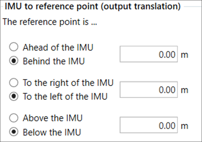
This is where you can add offset values to let the VBOX unit know where the reference point is relative to the IMU.
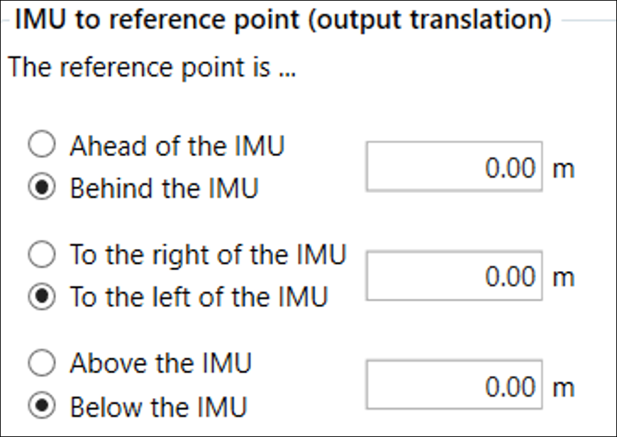
This is where you can add offset values to let the VBOX unit know where the reference point is relative to the IMU.
Note: These options are only presented when the Location is set as Internal.
The IMU orientation dictates which way the unit is facing and therefore dictates how the raw IMU channels are presented.
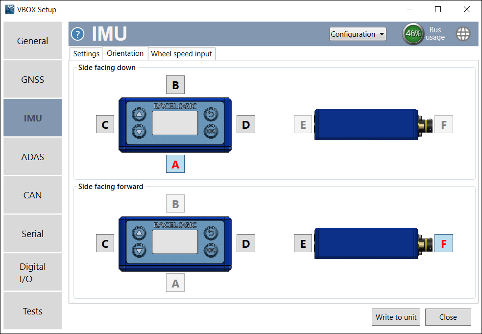
Select the appropriate letter for the orientation of the side of the VBOX unit that is facing down.
Select the appropriate letter for the side of the VBOX unit that is facing forward.
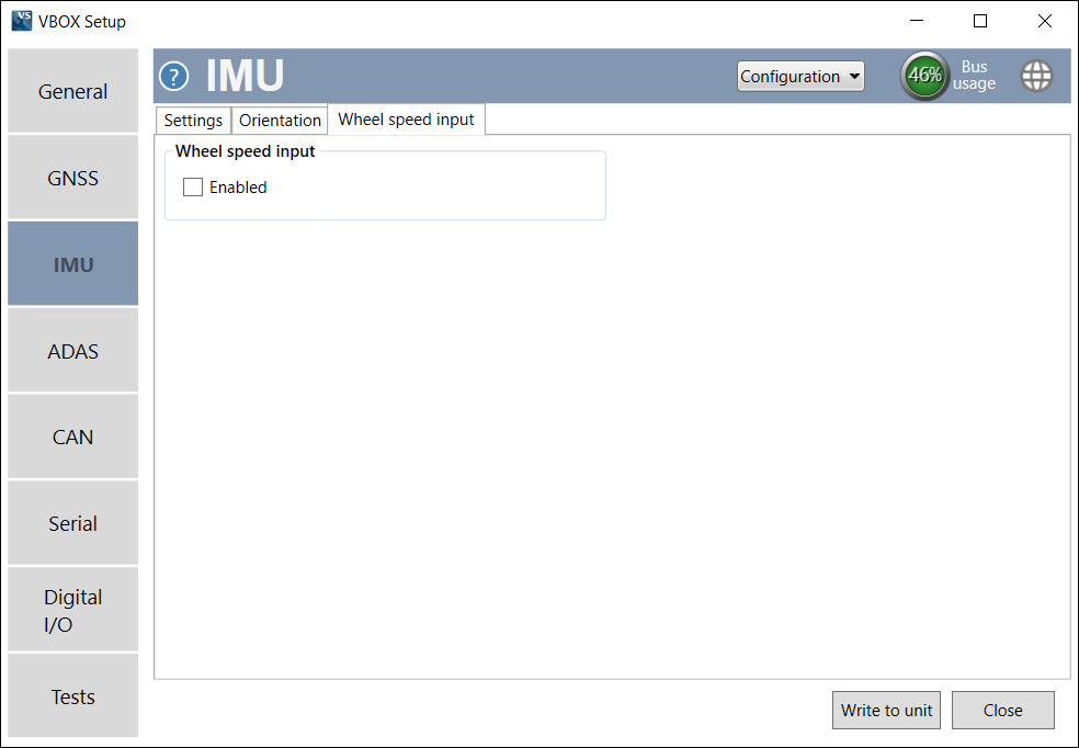
Note: This tab is only presented when you have set the IMU integration to Enabled.
The wheel speed input options can be used to configure the wheel speed input channels and the reference location.
Combining wheel speed information in the Kalman Filter can improve positioning in locations that are subject to obstacles. In areas where there is no view of the sky at all, such as tunnels, inertial sensors and wheel speeds can fill in the gaps for periods of up to 5 minutes. You can find more information about this here.
IMPORTANT
You must not use wheel speeds when you are conducting brake stop tests!
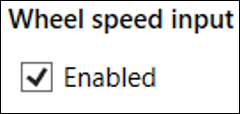
Enables the wheel speeds to be passed into the Kalman Filter. Adds Wheel Speeds channel to CAN ID 31D. If no CAN data is detected, a warning message is displayed on the front panel.

Enables the wheel speeds to be passed into the Kalman Filter. Adds Wheel Speeds channel to CAN ID 31D. If no CAN data is detected, a warning message is displayed on the front panel.
Note: The following options are only presented when Wheel speed input is Enabled.
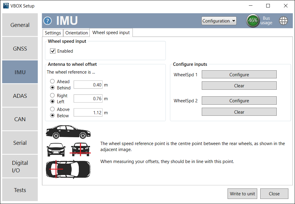
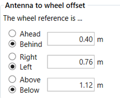
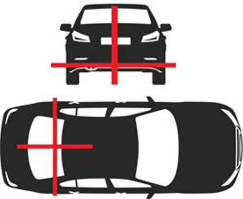
These offset values specify the x,y,z distances (m) between the wheel speed reference point and the antenna. The reference point is the centre point between the rear wheels, as shown in the image below.
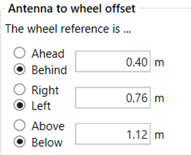
These offset values specify the x,y,z distances (m) between the wheel speed reference point and the antenna. The reference point is the centre point between the rear wheels, as shown in the image below.
Note: These options are only presented when Wheel speed input is Enabled.
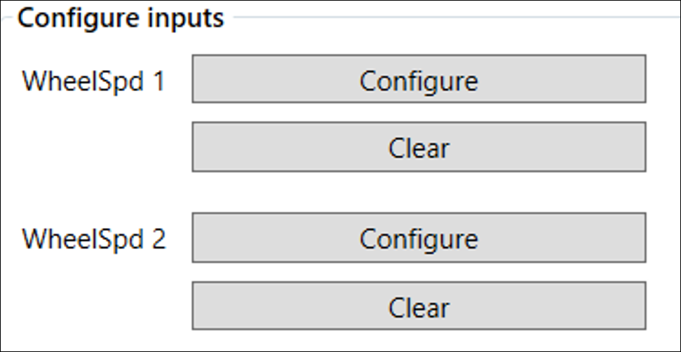
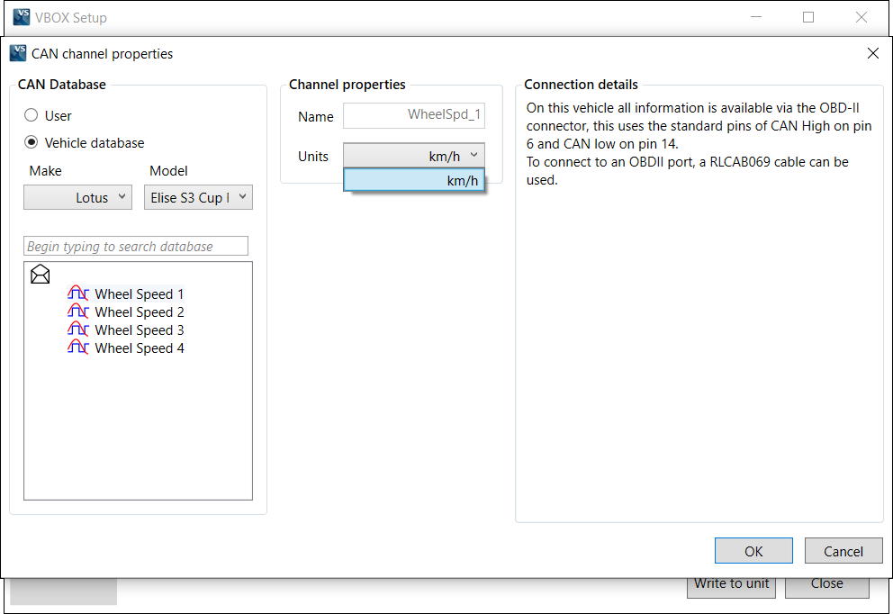
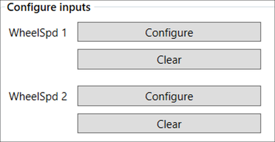
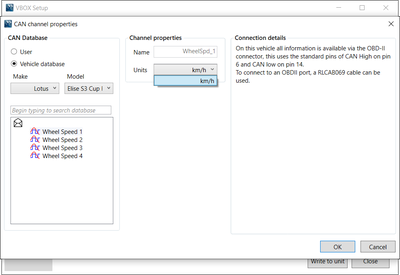
Wheel speed 1 and 2 Configure buttons open up the CAN setup area where you can load in a .dbc file or manually set up the CAN parameters by selecting the User option. Alternatively, selecting Vehicle database enables you to browse the Racelogic Vehicle CAN database within the software and select your vehicle. Once selected, CAN channels specific to your vehicle will appear on the left. If available, CAN connection information for the vehicle will also appear on the right of the window. Click on a wheel speed channel and click OK to save the configuration. Repeat for the other wheel speed channel.