GNSS measurement of speed, position and acceleration has become an essential part of the process in assessing the performance of many aspects of a vehicle. Test tracks are rarely perfect places for satellite reception, with trees, bridges and tunnels all having an effect on the quality of the measured data. When the tests are carried out on the road, this problem becomes even greater, with more objects obscuring the direct view to the satellites.
VBOX Omega can limit these obstacles by utilising the latest multi-frequency, multi-constellation GNSS receiver and integrating inertial and vehicle speed data.
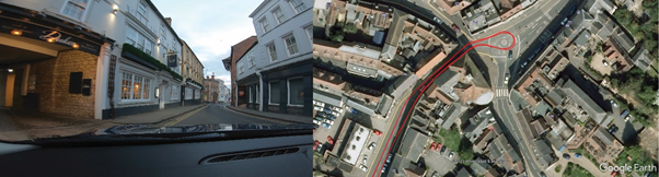
An added advantage of using multi-frequency techniques is that the time taken to recover accuracy after a bridge or tunnel is often less than 2 seconds. In areas where there is no view of the sky at all, such as tunnels, inertial sensors and wheel-speeds can fill in the gaps for periods of up to 5 minutes.
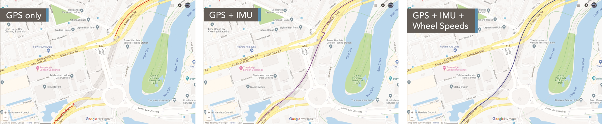
In the data above, you can clearly see the difference that the inertial and wheel-speed data is making to the accuracy of the estimated trajectory, with the IMU doing a good job of estimating the position during the tunnel, ending up with a 15 m error at the end (purple trace). Adding the wheel-speeds into the system (blue trace) significantly reduces the errors, tracking the vehicle through the tunnel with great accuracy.
To use wheel speeds, you must first configure VBOX Omega. You can do this either by using VBOX Setup or the menu on the Front panel.
Follow the steps below to set it up with the optimal configuration for use in urban areas.
- Make sure that the VBOX Omega unit is powered on.
- Connect VBOX Omega to a computer with the supplied loom:
Connect an RLCAB001 cable to the CONFIG lead and connect the serial plug to the computer's serial port – you can use a serial to USB convertor if required. - Open VBOX Setup and connect to VBOX Omega by selecting the correct COM Port.
- Open the IMU menu and the Settings tab.
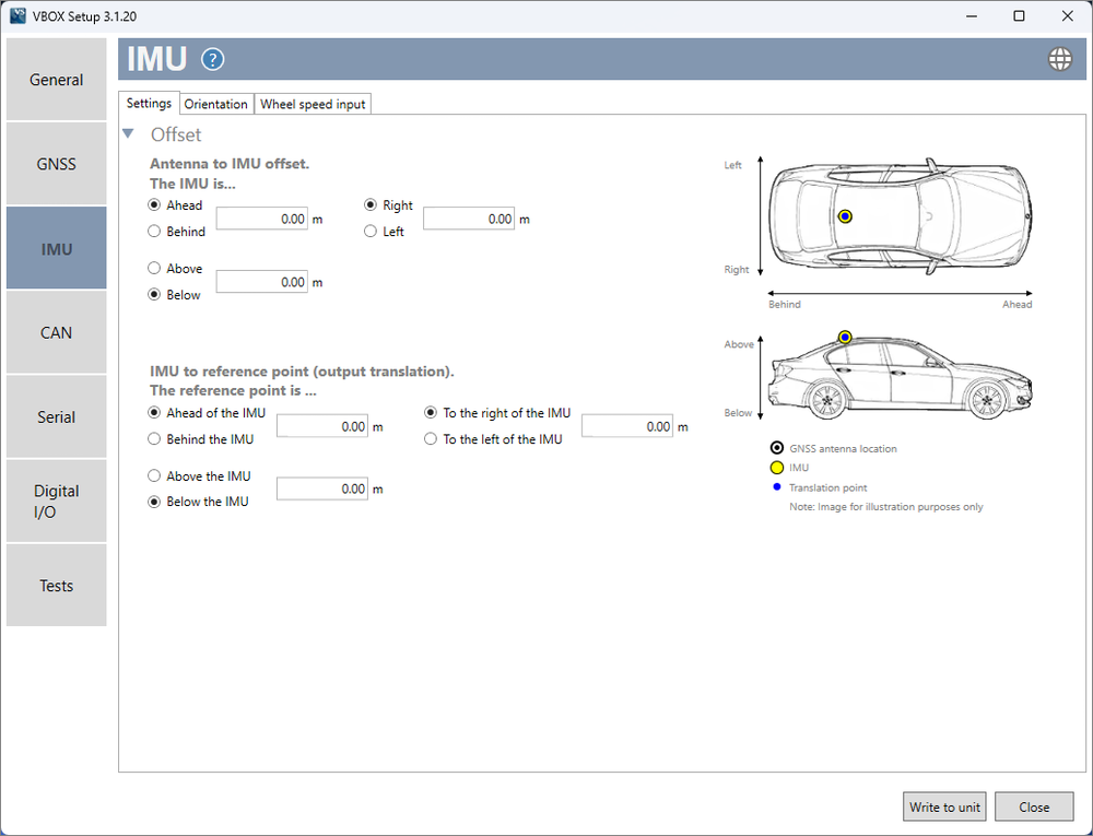
- Enter the Antenna to IMU/ reference offsets.
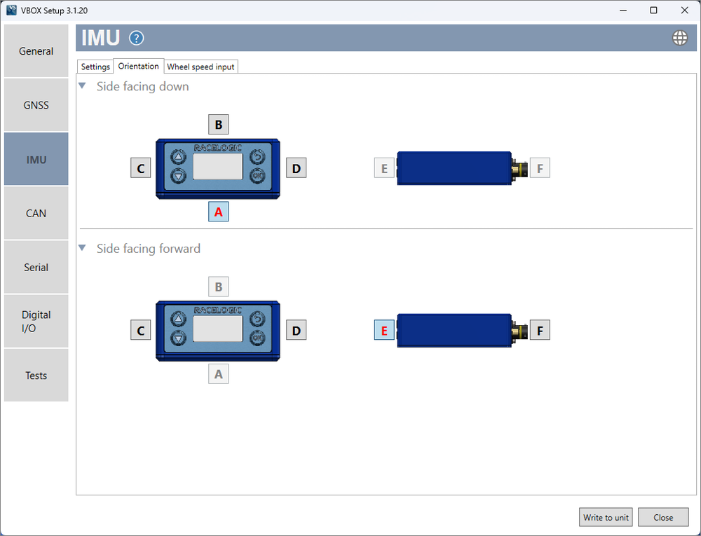
You can find more information on this here. - Select the Orientation tab and make sure that you select the correct sides of the unit facing down and forward.
- Click Write to unit to save the settings.
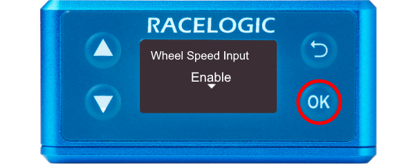
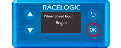
- Press the OK button to enter the menu, navigate to IMU using the Down arrow and then press the OK button.
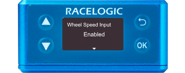
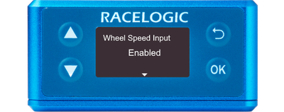
- Press the OK button again to Enable Wheel Speed Input.
- Enabled will then be displayed.
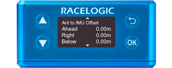
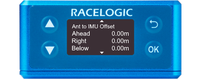
- Navigate to Ant to IMU/Ref. Offset using the Down arrow. Press the OK button to enter the menu.
- Use a combination of the Up and Down arrows and the OK button to enter the measured ahead/behind, right/left and above/below offset values.
You can find more information on this is here.
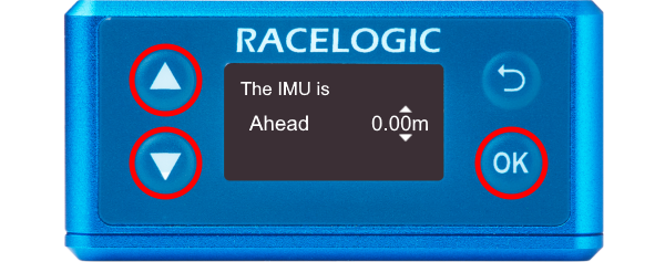
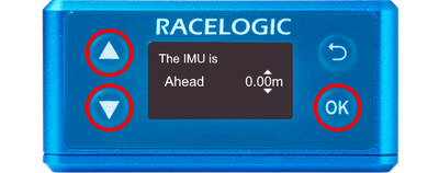
- Use the Down arrow to navigate to Side facing down and press the OK button to enter the menu. Use the Up and Down arrows to ensure the correct side is indicated and press the OK button to confirm. Repeat the process for Side facing forwd.
It is important to perform the full calibration procedure before meaningful testing commences. The calibration procedure is a series of specific manoeuvres that should be performed to help the Kalman Filter characterise the outputs from the IMU. More information on this is available here.
In order to obtain the wheel speed information, the best solution is to use the sensors already fitted to the vehicle by connecting to the vehicle’s CAN bus. Before testing commences, ensure that VBOX Omega is correctly connected to either the speed sensors or to the vehicle CAN bus using the CAN D type connector lead on the supplied loom.
- Make sure that the VBOX Omega unit is powered on.
- Connect VBOX Omega to a computer with the supplied loom:
Connect an RLCAB001 cable to the CONFIG lead and connect the serial plug to the computer's serial port – you can use a serial to USB convertor if required. - Open VBOX Setup and connect to VBOX Omega by selecting the correct COM Port.
- Open the IMU menu and select the Wheel speed input tab.
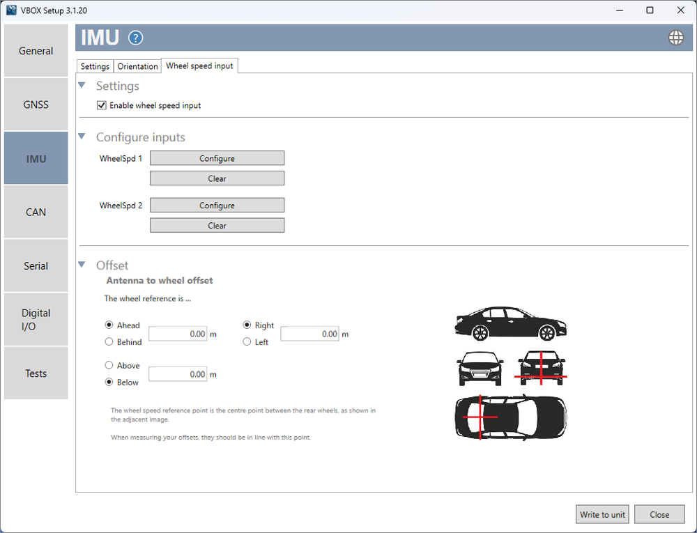
- Tick Enable wheel speed input in the Settings section.
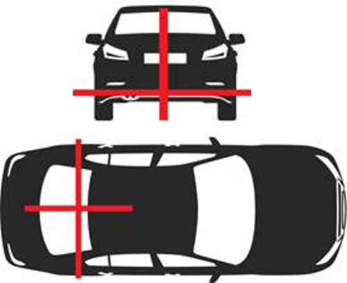
- Enter the Antenna to wheel offsets, these are the x, y and z distances (m) between the antenna and the wheel speed reference point. The reference point is the centre point between the rear wheels, as shown in the image below.
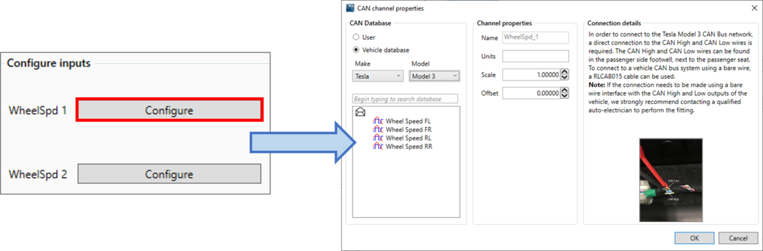
- Click the Configure buttons for Wheel speed 1 to open the CAN setup area.
This is where you can load a .dbc file or manually set up the CAN parameters by selecting the User option.
Alternatively, you can select Vehicle database to browse the Racelogic Vehicle CAN database and select your vehicle make and model. This will display the CAN channels specific to your vehicle on the left. If available, you will also see CAN connection information for the vehicle on the right side of the window.
- Click on a wheel speed channel to select it and click OK to save the configuration.
- Repeat for the other wheel speed channel.
- Select Write to unit to save the settings.
You may also need to adjust the Satellite Elevation Mask depending on the environment you are in.
You can find more information here.