The label on the top of the Wheel Speed Sensor will indicate the following:
- The wheel position on the vehicle.
- LF = Left Front
- LR = Left Rear
- RF = Right Front
- RR = Right Rear
- T1 and T2
- T1 = Temperature Input 1
- T2 = Temperature Input 2
These points to the K-type connectors on the side of the sensor unit to help you identify each temperature channel in the test data.
| Connector | Functionality |
|---|---|
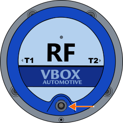
| Charging Port | Connect the sensor charger (WSCHAR) to this port to charge the internal sensor battery. |
CAUTION
To keep the stated waterproof rating of the Wheel Speed Sensor, you must securely close the charging port with the provided water plug to prevent water from entering the sensor during use.
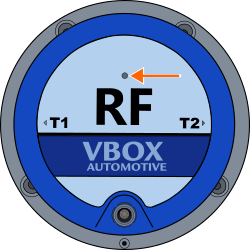
Located on the top of the Wheel Speed Sensor, above the text.

Solid Red - The sensor is booting up.

Solid Red - The sensor is booting up.

Solid Green - The sensor is operational.

Solid Green - The sensor is operational.
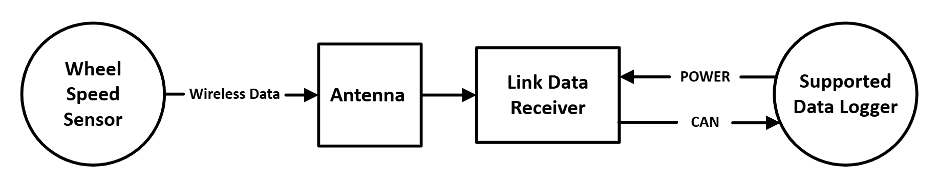
By connecting a thermocouple to one or both of the temperature inputs on the Wheel Speed Sensor, it can send the measured temperature data wirelessly to the data logger via the Link Data Receiver.
| Connector | Label | Functionality |
|---|---|---|
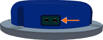
| K-Type | T1 / T2* | Connect a K-type thermocouple to T1 and/or T2 to measure and transmit temperature. |
*The connector label is located on the top of the sensor.
| Connector | Label | Functionality |
|---|---|---|
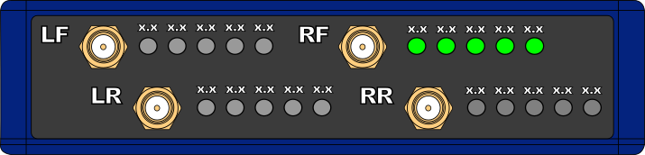
| SMA | LF | For connecting the receiver antenna(s) from each Wheel Speed Sensor. Make sure that you connect the antenna for each sensor to the correct SMA port. Example: Connect the antenna for the RF Wheel Speed Sensor to the RF SMA connector. |
| SMA | RF | |
| SMA | LR | |
| SMA | RR |
The front panel of the Link Data Receiver has 5 Sensor LEDs next to each SMA connector. The SMA connectors are labelled LF, LR, RF and RR.
These labels match the Wheel Speed Sensors labels. They specify the appropriate wheel position each sensor has on the vehicle (Left Front, Left Rear, Right Front and Right Rear). for the installation of the relevant Wheel Speed Sensor and the receiver antenna for the relevant Wheel Speed Sensor.
Green (solid) — One or more green LEDs show that the receiver receives data from the linked Wheel Speed Sensor.
Green (solid) — One or more green LEDs show that the receiver receives data from the linked Wheel Speed Sensor.
The Sensor LEDs show the battery level of the linked sensor. Each LED represents 20% of the battery charge.

Battery Level = 80-100%

Battery Level = 80-100%

Battery Level = 60-80%

Battery Level = 60-80%

Battery Level = 40-60%

Battery Level = 40-60%

Battery Level = 20-40%

Battery Level = 20-40%

Battery Level = 0-20%

Battery Level = 0-20%
| Connector | Label | Functionality |
|---|---|---|
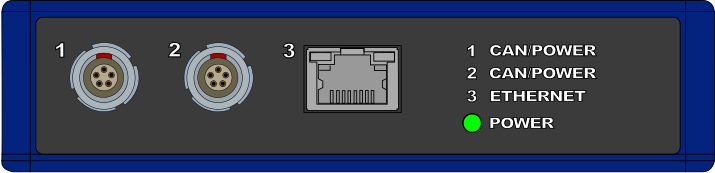
| Port 1 / Port 2* | CAN/POWER | Power and CAN connection to a compatible Data Logger, or CAN daisy-chain to other modules. |
| Port 3 | ETHERNET | Not used. |
*Ports 1 and 2 are bridged, use either to connect to the VBOX Data Logger.
Green (solid) - The receiver has power.
Green (solid) - The receiver has power.