A. RLACS173-XXX-V2 – Survey Trolley kit
(XXX represents the kit variant)
A1. Telemetry Antenna (depends on the kit variant)
A2. Telemetry Antenna Extension Cable (SMA to SMA) (If applicable)
A3. Antenna Offset Bracket
A4. 5/8” Stainless Steel Nut x2
A5. Extension Pole
A6. Battery Pack
A7. Surveying Rucksack
A8. Rover wheels (preassembled subassembly)
A9. Rover wheel handle (with washers and stainless-steel bolt)
A10. Rover Wheel Pointer
B. Equipment Supplied Separately
(as part of your VBOX data logger, Telemetry Radio, or Ground Plane Antenna Kit)
B1. ADAS-compatible VBOX Data Logger
B2. VBOX Telemetry Module
B3. GNSS Ground Plane Antenna
B4. Ground Plane Antenna Cable (supplied with the antenna)
B5. Telemetry to VBOX Cable (supplied with the Telemetry module)
B6. Compatible Media (Supplied with the VBOX Data Logger)
C. Tools (Not supplied)
- Spanner (8 mm)
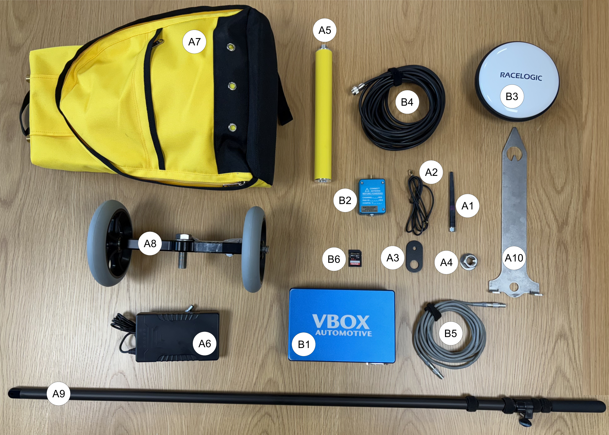
Figure 1: Example of required equipment
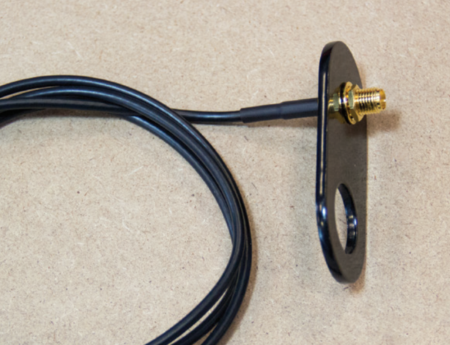
- If required, remove the small nut and washer from the male connector on the Antenna Extension Cable (A2). Insert the connector through the smallest hole in the Antenna Offset Bracket (A3).
- Refit the washer and nut and tighten with an 8mm spanner.
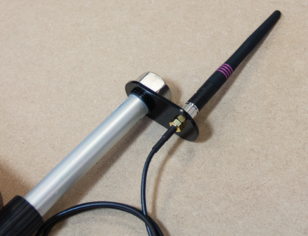
- Attach the Telemetry Antenna (A1) to the Antenna Extension Cable (A2) on top of the Antenna Offset Bracket (A3).
- Remove the Extension Pole (A5) from the Surveying Rucksack (A7) and take off the plastic end cap.
- Secure the Antenna Offset Bracket (A3) to the top of the Extension Pole (A5) using the supplied stainless-steel nut.


- Attach the Extension Pole (A5) to the Surveying Rucksack (A7).
- Route the Antenna Extension Cable (A2) into the interior of the Surveying Rucksack (A7).
- Connect the female end of the Antenna Extension Cable (A2) to the SMA port on the VBOX Telemetry module (B2).
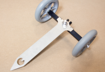
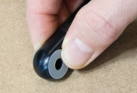
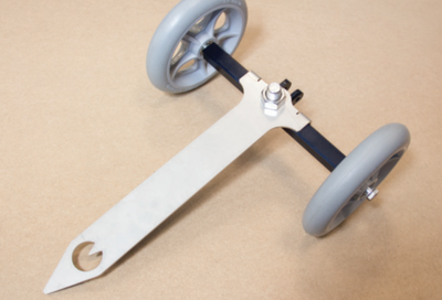
- Place the Rover Wheel Pointer (A10) onto the Rover Wheels (A8) by inserting the threaded bolt on the wheel axle through the central, round hole in the Pointer. Make sure that the corner brackets face downward around the axle, and the pointed end faces forward in the direction of travel.
- Secure the Rover Wheel Pointer using the supplied stainless-steel nut.
- Insert the end of the Rover Wheel Handle (A9) with the mounting hole (and washers) into the bracket on the Rover Wheels (A8) axle. Align the holes and secure the handle by inserting the supplied bolt through the bracket and handle.
Note: Make sure a washer is fitted on each side of the handle before you insert the bolt. Do not over-tighten.

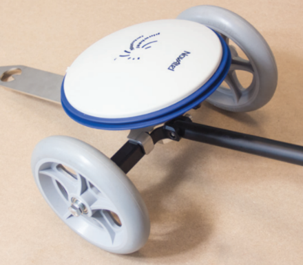
- Screw the Ground Plane Antenna (B3) onto the protruding bolt at the top of the Rover Wheel Pointer (A10).
Note: Align the antenna connector so that it faces the same direction as the Rover Wheel Handle (A9).
- Connect the VBOX Telemetry module (B2) to the VBOX Data Logger (B1) with the Telemetry-to-VBOX Cable (B5).
- Connect the Battery Pack (A6) to the power port on the VBOX Data Logger (B1).
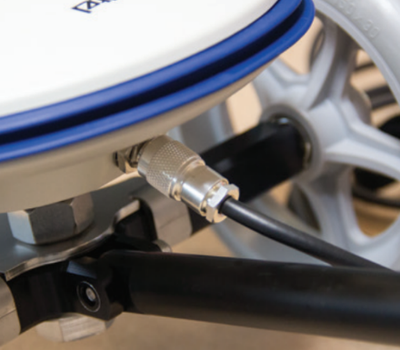
- Connect the Ground Plane Antenna (B3) to the Antenna Port on the VBOX Data Logger using the Ground Plane Antenna Cable (B4).


- Secure all equipment in the Surveying Rucksack (A7) and attach the antenna cables to the telescopic pole using the supplied Velcro wraps.