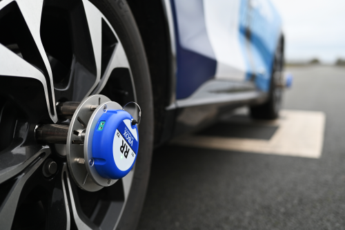
Accurately measure wheel speeds up to 100 times a second, with universal installation suitable for a range of vehicle types.
- Wireless technology ensures easy and fast installation
- Built-in thermocouple input for brake disc temperature measurement
- Straightforward integration with data loggers via CAN output
This Quick Start Guide covers specific steps for installing, powering, configuring, and running your first test. It covers the simplest and quickest connection and configuration, using VBOX 4 as the data logger. For full details about using the Wireless Wheel Speed Sensors, see the Wireless Wheel Speed Sensors User Guide.
The mounting steps in this guide apply to all system installations. The receiver connection and configuration steps will depend on the system's data logger.
For other supported data loggers, the required information is in the list of relevant links.
IMPORTANT
- Activate the sensors while the vehicle is stationary. This allows the sensor to calculate internal bias and set zero.
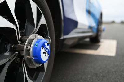
- The sensors and corresponding antennas must be installed and connected based on the relevant wheel position:
LF = Left Front
LR = Left Rear
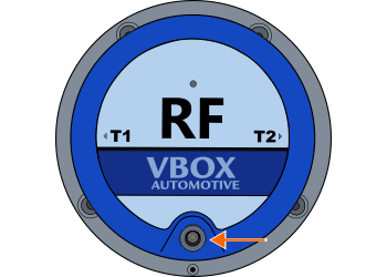
RF = Right Front
RR = Right Rear
CAUTION
- To keep the stated waterproof rating of the Wheel Speed Sensor, you must securely close the charging port with the port cover (water plug) to prevent water from entering the sensor.
- Mount the sensors securely. Do not start the test if the mounting plate can move by hand.
This section lists the equipment you need to complete the steps in this Quick Start Guide.
Sensors
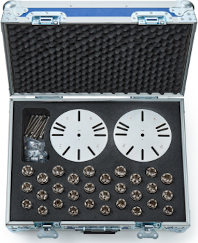
Fixture Kit
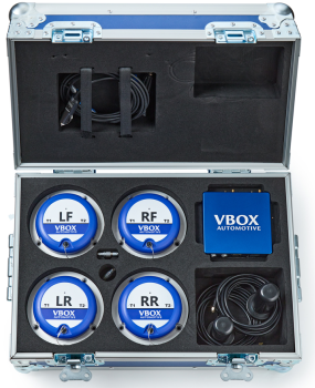


You need these items to install and use Wireless Wheel Speed Sensors:
- Link Data Receiver (WS-REC)
- Wheel Speed Sensors
(quantity depends on kit and test requirements)
- Wheel Speed Sensor Receiver Antennas
(one antenna per required sensor)
- Magnetic Switch (WSMAGSW)
(to activate the sensors)
You need the fixture kit to mount the sensors to a vehicle wheel:
- Wheel Nut Split Collets with Collars
(Select the correct size for the wheel nuts on the test vehicle: 17/19/20 mm) - Flange Plate
(mounting plate) - Wheel mounting spacers
- Wheel mounting bolts (5 mm)
- Sensor mounting screws (3 mm)
- Allen keys (5 mm and 3 mm)
For the full kit contents list, see Getting Started – Package Contents.
- Supported data logger. (This Quick Start Guide covers wheel speed sensor configuration for VBOX 4.)
- VBOX 4 Power Supply.
- VBOX 4 GNSS Antenna.
- Laptop/PC with VBOX Setup installed. (For configuration and calibration.)
- USB cable RLCAB042. (For VBOX 4 USB connection.)
This Quick Start Guide only covers connection and configuration information for the Wireless Wheel Speed Sensors specifically. See the VBOX 4 User Guide for your VBOX 4 data logger to find required connection and configuration information for the full system.
You may also need these items, depending on your system:
- K-type thermocouples - for temperature logging if required
- Tools - the following tools may be useful during the installation:
- Mallet (for seating wheel nut split collets)
- Cleaning cloth (for wheel nut surfaces)
- Cable ties (for securing antenna cables)
This section provides information about the available conntectors and LEDs on the Wheel Speed Sensors and the Link Data Receiver.
Click on a heading to see more information:


| Connector | Functionality | |
|---|---|---|
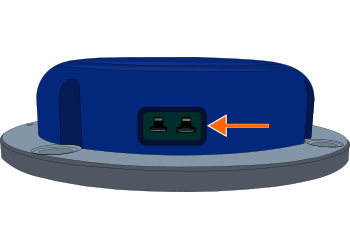
| Charging Port | N/A | Connect the sensor charger (WSCHAR) to this port to charge the internal sensor battery |
| K-Type | T1 / T2* | Connect a K-type thermocouple to T1 and/or T2 to measure and transmit temperature. |

Solid Red - The sensor is booting up.

Solid Red - The sensor is booting up.

Solid Green - The sensor is operational.

Solid Green - The sensor is operational.

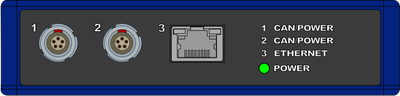
| Connector | Label | Functionality |
|---|---|---|
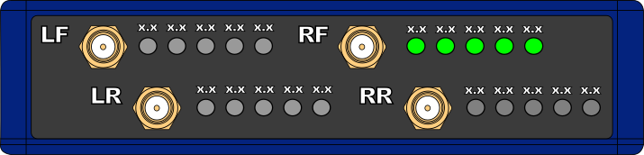
| SMA | LF /RF /LR /RR | Connect one receiver antenna per used wheel speed sensor, the antenna mounted near the right front wheel should be connected to the SMA connector labelled RF. |
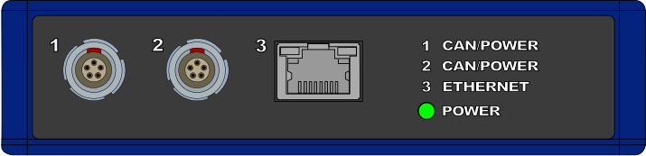
| Port 1 / Port 2* | CAN/POWER | Power and CAN connection to a compatible Data Logger, or CAN daisy-chain to other Modules. |
| Port 3 | ETHERNET | Not used. |
*Ports 1 and 2 are bridged, use either to connect to the VBOX Data Logger.
The front panel of the Link Data Receiver has 5 Sensor Link/Battery LEDs next to each SMA connector.
Green (solid) — One or more green LEDs show that the receiver receives data from the linked Wheel Speed Sensor.
The Sensor LEDs show the battery level of the linked sensor. Each LED represents 20% of the battery charge.
Green (solid) — One or more green LEDs show that the receiver receives data from the linked Wheel Speed Sensor.
The Sensor LEDs show the battery level of the linked sensor. Each LED represents 20% of the battery charge.
- Select the required size of wheel nut split collets and collars.
- Place one split collets on each wheel nuts on the wheel and seat the collets level.
- Place the collars over the split collets.
- Get the mounting plate (flange plate) and identify the mounting slots by the wheel nut count.
- Place the mounting plate on top of the split collets and collars in the correct orientation.
- Insert the required number of wheel mounting bolts with wheel mounting spacers through the mounting holes in the plate and into the top of the split collet collars.
- Tighten the wheel mounting bolts until the plate cannot move by hand.
- Select the correct sensor for the wheel position on the vehicle and fix it on top of the mounting plate with the 3-mm mounting screws.
- Insert the water plug into the charging port (waterproof).
- Repeat for each required sensor.
For full mounting steps, slot diagrams, and locking nut guidance, see Mounting with Fixture Kit (WSFIX[X]).
Antenna Placement
- Place one antenna near each mounted sensor.
- Make sure the antennas are placed away from sources of 2.4 GHz interference.
- Make sure the antennas have a clear line of sight to the sensor.
Antenna Connection
Connect the antenna cables to the SMA connectors on the Link Data Receiver. The label on the SMA connector must match the antennas position on the vehicle (right front, right rear, left front or left rear).
Note: Sensors can send data using the internal antenna. Use the supplied receiver antennas to improve signal strength and reduce data loss.
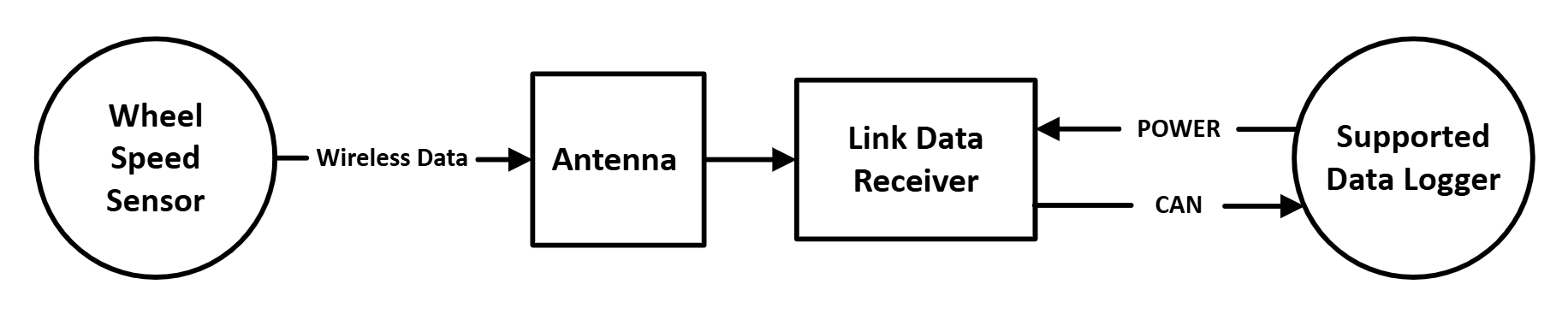
- Power the Link Data Receiver by connecting it to the data logger.
- Activate each Wheel Speed Sensor with the Magnetic Switch (WSMAGSW).
- Check LEDs:
- Sensor Status LED: green
- Relevant Sensor Link/Battery LEDs : green
This section contains information about how to configure and calibrate the connected Wheel Speed Sensors before a test.
- Power the VBOX 4 data logger.
- Connect the VBOX 4 unit to a PC with VBOX Setup installed.
- Start VBOX Setup and connect to the data logger.
- Open the Channel Setup menu.
- Click on the Wheel Speed Sensor section heading in the list of available CAN Input sources.
- Select the Wheel Speed Sensor channels you want to log.
Use the Auto-Calibrate feature to convert wheel speed (RPM) into vehicle speed.
- Click Calibrate to start.
- Accelerate to the target speed.
- Drive in a straight line.
VBOX Setup starts a 5-second countdown when it detects the correct speed and heading (the direction of travel as reported by the GPS).
When the countdown finishes, VBOX Setup applies scale factors and completes calibration.
Note: VBOX Setup scales channels to km/h. VBOX Test Suite can convert units.
For full configuration and calibration steps, see: Configuration.
When you have completed the installation and configuration as described in this guide, and you have calibrated the sensors, the system is ready for wheel speed testing.
- Start logging on the VBOX 4 data logger.
- Perform the test as required.
- Stop logging and review the results in VBOX Test Suite.
See the relevant VBOX 4 User Guide for more information about starting and stopping logging during testing.
Receiver does not receive data
- Check that the sensors are active (Sensor Status LED is green).
- Check that each antenna connects to the correct SMA port (LF/LR/RF/RR).
- Move the antenna closer to the sensor and remove obstructions.
Sensor does not activate
- Swipe the Magnetic Switch over the top of the sensor again.
- Charge the sensor battery if required.
Waterproof rating concern
- Fully insert the port cover into the charging port.
For more troubleshooting, see: Troubleshooting.