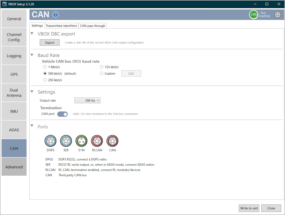
The CAN menu is where you can export .dbc files, set the CAN baud rate, set the output rate, set the CAN termination and configure and enable full bus logging for the CAN FD ports.
In the top right-hand corner of the CAN menu, you will see this Bus loading graphic.
It will display the current load on the CAN bus, so you can see the load applied to the bus as you add channels. We recommend a maximum load of 70%. If the CAN bus loading exceeds the recommended 70%, the CAN bus may become unstable and samples may be lost. You can reduce the bus load by increasing the baud rate or reducing the number of output IDs.


Export
Click Export to create a .DBC file of the current VBOX CAN output configuration.
Click on a port to expand the port settings.


Baud Rate
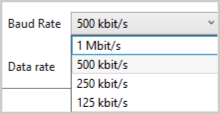
The baud rate sets the bit rate of the CAN messages (not the frequency at which the messages are sent).
The default setting is 500 Kbit/s as most light vehicles use that baud rate.
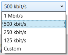
The available baud rate options are:
- 1 Mbit/s
- 500 kbit/s
- 250 kbit/s
- 125 kbit/s
- Custom
The baud rate sets the bit rate of the CAN messages (not the frequency at which the messages are sent).
The default setting is 500 Kbit/s as most light vehicles use that baud rate.
The available baud rate options are:
- 1 Mbit/s
- 500 kbit/s
- 250 kbit/s
- 125 kbit/s
- Custom

Custom Baud Rate
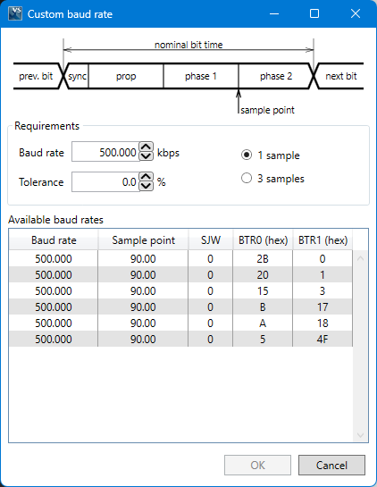
If you wish to use another baud rate than the specific baud rate settings, you can select the Custom option and click the Edit button. This will open a window where you can set your own custom baud rate.
Output Rate
This setting controls the CAN output update rate for the purpose of resolving bandwidth limitation issues.
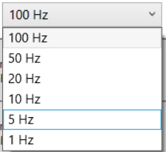
The available output rates are:
- 100 Hz
- 50 Hz
- 20 Hz
- 10 Hz
- 5 Hz
- 1 Hz
This setting controls the CAN output update rate for the purpose of resolving bandwidth limitation issues.
The available output rates are:
- 100 Hz
- 50 Hz
- 20 Hz
- 10 Hz
- 5 Hz
- 1 Hz

Termination
Ticking the Termination box will add 120-ohm resistance to the CAN bus connection.

Ticking the Termination box will add 120-ohm resistance to the CAN bus connection.

Note: If you add or remove termination on the CAN port, you must power-cycle the VBOX after writing the settings to the unit.
Configure CAN Input
Click on the Configure CAN Input button to open the CAN Input section in the Channel Setup menu to further configure your CAN channels.
Click on the Configure CAN Input button to open the CAN Input section in the Channel Setup menu to further configure your CAN channels.


Full Bus Logging
Enable CAN logging on the CAN FD 1 port by toggling the Full bus logging switch on.
When the bus is active, the applied settings will be displayed in the grey section heading.

Enable CAN logging on the CAN FD 1 port by toggling the Full bus logging switch on.
When the bus is active, the applied settings will be displayed in the grey section heading.

Bus Name
The default name for the bus is CAN FD 1 but you can edit the name in the text box.

The default name for the bus is CAN FD 1 but you can edit the name in the text box.

Termination
The Termination toggle switch will enable/disable 120-ohm resistance to the CAN bus connection on the CAN FD 1 port.
The Termination toggle switch will enable/disable 120-ohm resistance to the CAN bus connection on the CAN FD 1 port.
Note: If you add or remove termination on the CAN port, you must power-cycle the VBOX after writing the settings to the unit.
Baud Rate
The baud rate sets the bit rate of the CAN messages (not the frequency at which the messages are sent).
The default setting is 500 Kbit/s.
The available baud rate options are:
- 1 Mbit/s
- 500 kbit/s
- 250 kbit/s
- 125 kbit/s

The baud rate sets the bit rate of the CAN messages (not the frequency at which the messages are sent).
The default setting is 500 Kbit/s.
The available baud rate options are:
- 1 Mbit/s
- 500 kbit/s
- 250 kbit/s
- 125 kbit/s
CAN FD
The CAN FD toggle switch enables/disables the CAN FD logging on the CAN FD 1 port.
When you enable this setting, the Data rate setting becomes available.
When this setting is disabled, the CAN FD 1 port will only log CAN 2.0.

The CAN FD toggle switch enables/disables the CAN FD logging on the CAN FD 1 port.
When you enable this setting, the Data rate setting becomes available.
When this setting is disabled, the CAN FD 1 port will only log CAN 2.0.

Data Rate
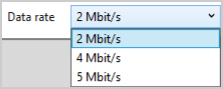
When you are logging CAN FD, you will also need to define the required data rate.
The available data rate options are:
- 5 Mbit/s
- 4 Mbit/s
- 2 Mbit/s

When you are logging CAN FD, you will also need to define the required data rate.
The available data rate options are:
- 5 Mbit/s
- 4 Mbit/s
- 2 Mbit/s
Configure CAN FD 1 Input
Click on the Configure CAN FD 1 Input button to open the CAN FD 1 Input section in the Channel Setup menu to further configure your CAN channels.

Click on the Configure CAN FD 1 Input button to open the CAN FD 1 Input section in the Channel Setup menu to further configure your CAN channels.


Full Bus Logging
Enable CAN logging on the CAN FD 2 port by toggling the Full bus logging switch on.
When the bus is active, the applied settings will be displayed in the grey section heading.
Enable CAN logging on the CAN FD 2 port by toggling the Full bus logging switch on.
When the bus is active, the applied settings will be displayed in the grey section heading.
Bus Name
The default name for the bus is CAN FD 2 but you can edit the name in the text box.

The default name for the bus is CAN FD 2 but you can edit the name in the text box.

Termination
The Termination toggle switch will enable/disable 120-ohm resistance to the CAN bus connection on the CAN FD 2 port.
The Termination toggle switch will enable/disable 120-ohm resistance to the CAN bus connection on the CAN FD 2 port.
Note: If you add or remove termination on the CAN port, you must power-cycle the VBOX after writing the settings to the unit.
Baud Rate
The baud rate sets the bit rate of the CAN messages (not the frequency at which the messages are sent).
The default setting is 500 Kbit/s.
The available baud rate options are:
- 1 Mbit/s
- 500 kbit/s
- 250 kbit/s
- 125 kbit/s
The baud rate sets the bit rate of the CAN messages (not the frequency at which the messages are sent).
The default setting is 500 Kbit/s.
The available baud rate options are:
- 1 Mbit/s
- 500 kbit/s
- 250 kbit/s
- 125 kbit/s
CAN FD
The CAN FD toggle switch enables/disables the CAN FD logging on the CAN FD 2 port.
When you enable this setting, the Data rate setting becomes available.
When this setting is disabled, the CAN FD 2 port will only log CAN 2.0.
The CAN FD toggle switch enables/disables the CAN FD logging on the CAN FD 2 port.
When you enable this setting, the Data rate setting becomes available.
When this setting is disabled, the CAN FD 2 port will only log CAN 2.0.
Data Rate
When you are logging CAN FD, you will also need to define the required data rate.
The available data rate options are:
- 5 Mbit/s
- 4 Mbit/s
- 2 Mbit/s
When you are logging CAN FD, you will also need to define the required data rate.
The available data rate options are:
- 5 Mbit/s
- 4 Mbit/s
- 2 Mbit/s
Configure CAN FD 2 Input
Click on the Configure CAN FD 2 Input button to open the CAN FD 2 Input section in the Channel Setup menu to further configure your CAN channels.

Click on the Configure CAN FD 2 Input button to open the CAN FD 2 Input section in the Channel Setup menu to further configure your CAN channels.

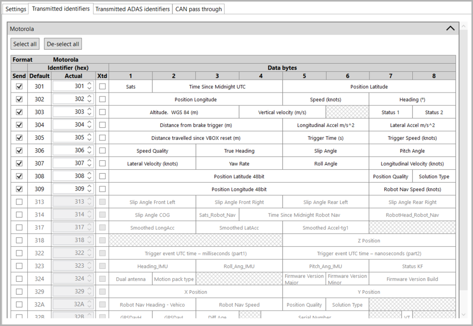
Select which CAN output identifiers you would like to have transmitted. The top table contains Motorola format CAN messages, the bottom table contains Intel format CAN messages, which are to be used with Stahle robot systems.
Select all
Click this button to tick all available Send boxes.
De-select all
Click this button to untick all ticked Send boxes.
Send
Tick or untick the respective Send boxes for the messages you wish to switch on or off.
Default and Actual ID
You can modify the CAN IDs transmitted by the VBOX. The Default values are the Racelogic standard IDs, for example, 0x301, 0x302 …. 0x307.
Xtd
Tick the respective Xtd boxes for the identifiers you wish to extend from the standard 11-bit format to the extended 29-bit format.
If it is unticked, the CAN identifier type will be standard 11 bit. The standard identifier type allows 2048 different CAN message identifiers or message “names”. The extended identifier type allows 436207616 different CAN message identifiers. The identifier type should be set to match the CAN data logging equipment.
Shows which channels will be sent out in each message.
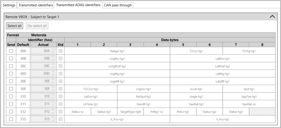
Select which ADAS CAN output identifiers you would like transmitted.
Note: This tab will only be available when you have enabled ADAS mode.
Select all
Click this button to tick all available Send boxes.
De-select all
Click this button to un-tick all ticked Send boxes.
Send
Tick or un-tick the respective Send boxes for the messages you wish to switch on or off.
Default and Actual ID
You can modify the CAN IDs transmitted by the VBOX by typing in a new ID or using the up and down arrows to move through the available IDs. If the selected ID is a duplicate of an already used one, it will become red to indicate it is unavailable. The Default values are the Racelogic standard IDs, such as 0x30A, 0x30B … 0x30F.
Xtd
Tick the respective Xtd boxes for the identifiers you wish to extend from the standard 11-bit format to the extended 29-bit format.
Shows which channels will be sent out in each message.
Select all
Click this button to tick all available Send boxes.
De-select all
Click this button to untick all ticked Send boxes.
Send
Tick or untick the respective Send boxes for the messages you wish to switch on or off.
Default and Actual ID
You can modify the CAN IDs transmitted by the VBOX. The Default values are the Racelogic standard IDs, for example, 0x301, 0x302 …. 0x307.
Xtd
Tick the respective Xtd boxes for the identifiers you wish to extend from the standard 11-bit format to the extended 29-bit format.
If it is unticked, the CAN identifier type will be standard 11 bit. The standard identifier type allows 2048 different CAN message identifiers or message “names”. The extended identifier type allows 436207616 different CAN message identifiers. The identifier type should be set to match the CAN data logging equipment.
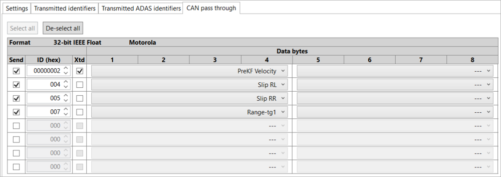
Note: If you are loading configuration settings from a previously saved .RCF file and external modules were connected during the save, selected CAN pass-through channels may not be reloaded correctly. Please check and manually configure these channels in VBOX Setup.