Video VBOXs can connect to the CAN bus of your vehicle to log and display additional parameters such as RPM, Throttle angle and Brake pressure. In order to do this, the protocol for the particular vehicle must be entered into the Scene Properties under CAN and module configuration.
If you wish to connect to your vehicles CAN bus system, please download the relevant CAN file from the Racelogic website. If you are bringing in CAN data from another VBOX system, CAN DBC files can be found on our VBOX DBC page.
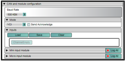
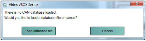
Once you have the correct CAN file, to setup a CAN channel for your vehicle, click on Load under Inputs.
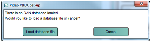
Now click on Load database file and select the file for your vehicle.
Some CAN files available are for multiple vehicles. The vehicle make is defined in the first 3 characters of the parameter, such as POR for Porsche, REN for Renault etc. Some cars are listed by the model.
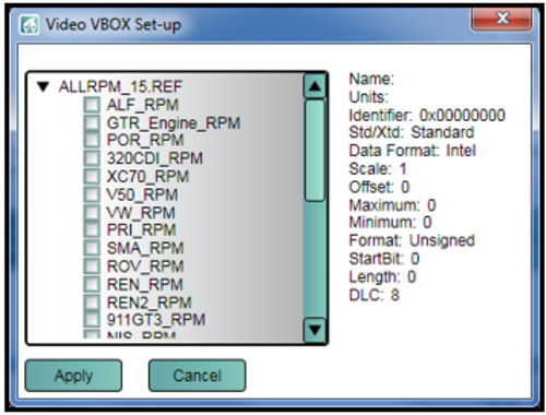
Select the closest match to your vehicle and click Apply. A CAN channel will then be assigned to this CAN message.
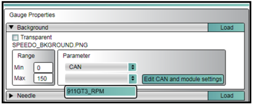
To display a CAN channel, select the chosen Element, Open the Element’s properties and select CAN from the pull down list under Parameter.
A list of all the defined CAN channels should then appear below, select the channel you wish to display.
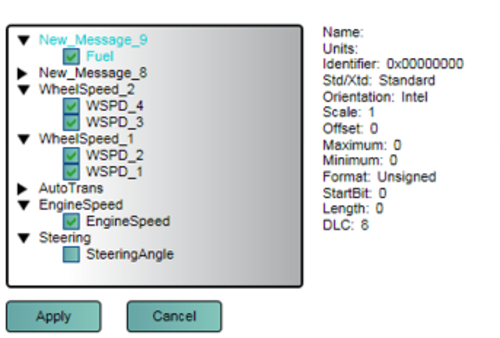
Under CAN and module configuration, select Load, and then Load database file.
Your Database file will then be displayed and you can tick the boxes alongside the message you wish to assign to a CAN channel. If you tick multiple boxes, then multiple CAN channels will be assigned.
The CAN channel can then be assigned to an Element in the same way as described above.
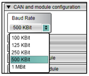
The default Baud rate of the Video VBOX is set at 500 kbit, the user has the option of selecting 100, 125, 250 or 500 kbit, and 1 Mbit.
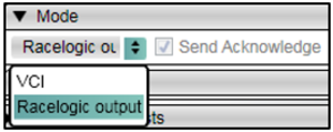
The VCI CAN mode should be selected if the Video VBOX is to be connected to a vehicle CAN bus.
The VCI CAN mode + Send acknowledge box should be selected if the Video VBOX is to be connected to any modules such as the ADC03.
The Racelogic Output mode should be selected if the Video VBOX is to be connected to a CAN logging device. If this mode is selected, the Video VBOX will transmit GPS channel data onto the CAN bus in this standard format.
Send Acknowledge: Racelogic modules and other CAN data-loggers and sensors require an acknowledge pulse to be sent. However, it is not recommended to send these messages when connected to a vehicle’s CAN bus.
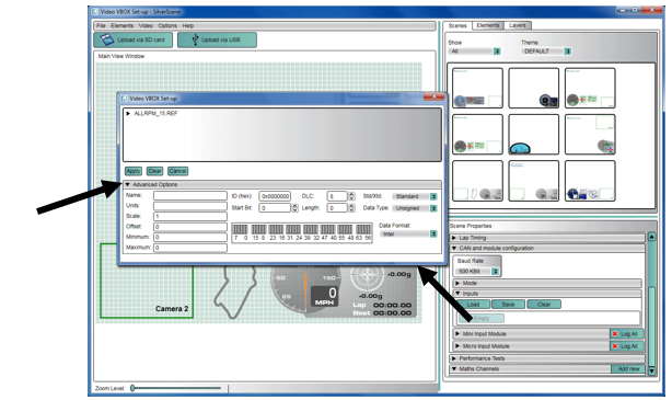
If you know the format of the CAN messages you wish to log, then click on the CAN channel that is to be modified and click Advanced Options.
Raw CAN data can be logged and assigned to a Text Parameter element. A CAN database is not required.
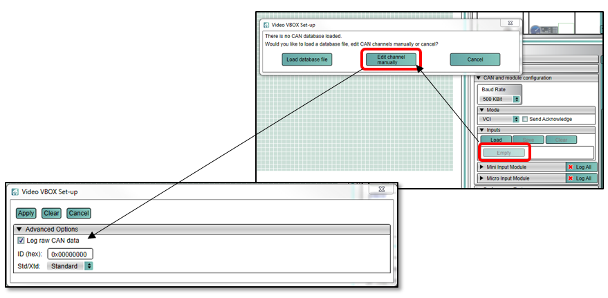
To set up a Raw CAN channel, ensure that VCI mode is selected, Send Acknowledge is un-checked and Baud Rate correctly set. Select an Empty Input Channel and then Edit channel manually.
Check the Log raw CAN data check-box and enter the ID to be logged. Click Apply and the channel will be available to assign to a Text Parameter element.
NOTE
Raw CAN data will only be displayed on the overlay. The Raw CAN channels are not compatible with VBOX Tools Software.
If the Video VBOX is to be used to log and display CAN data from the vehicle, the Video VBOX needs to be connected to the vehicle’s OBD (On-Board Diagnostics) port or directly into the CAN bus depending on the model. Most vehicles have an OBD connector which provides this interface.
The exact location of the OBD connector varies from vehicle to vehicle, but it will be within a few feet of the driver and it will have easy access. Most often you can find your OBD connector somewhere below the steering column, either above the pedals or perhaps inside a fuse box by the driver's knee. Your OBD connector will probably be in plain view, but some connectors are covered.
The Racelogic CAN database files can be downloaded from the Racelogic website.
NOTE
If the connection needs to be made using a bare wire interface with the CAN Hi and Lo outputs of the vehicle, we strongly recommend contacting a qualified auto-electrician to perform the fitting.