You can access the menu by pressing the OK button. Use the Up and Down arrows to navigate through the menu and press the OK button to enter a submenu or change a setting. When you edit a setting, the Up and Down buttons will let you scroll through the available options for that setting and the OK button will confirm your selection. Use the Back button to exit a setting.
This menu can be used to configure the internal/external IMU settings.
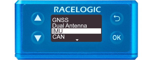
This menu can be used to configure the internal/external IMU settings.

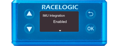
This setting enables IMU integration.
This action will add IMU channels to CAN ID 31B and 31C.
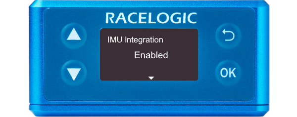
This setting enables IMU integration.
This action will add IMU channels to CAN ID 31B and 31C.
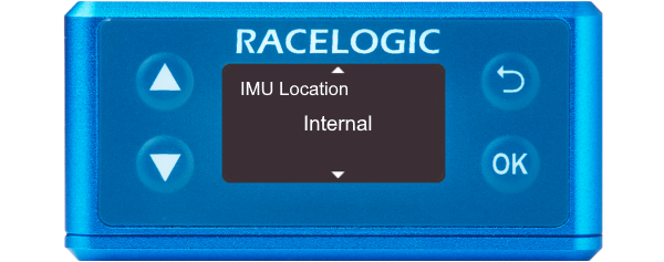
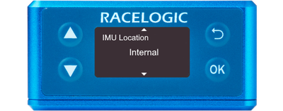
This setting specifies whether the speed sensor will be using its in-built IMU or an external IMU.
Notes:
- This option is only presented when the IMU integration is Enabled.
- When you change the IMU Location, the offset sections will be reset.
This setting specifies whether the speed sensor will be using its in-built IMU or an external IMU.
Notes:
- This option is only presented when the IMU integration is Enabled.
- When you change the IMU Location, the offset sections will be reset.
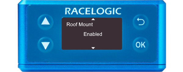
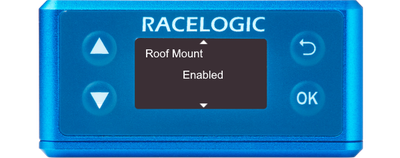
This setting specifies whether you are using a roof-mounted IMU from Racelogic or not. You should enable this when you have an external IMU installed on the roof mount that the primary antenna is mounted on
When it is Enabled, it will automatically configure an Antenna to IMU offset to account for the 3 cm distance between the IMU and Antenna on the Roof Mount and the Ant to IMU Offset setting will become Ant to Ref. Offset.
Note: This option is only presented when the IMU Location is set to External.
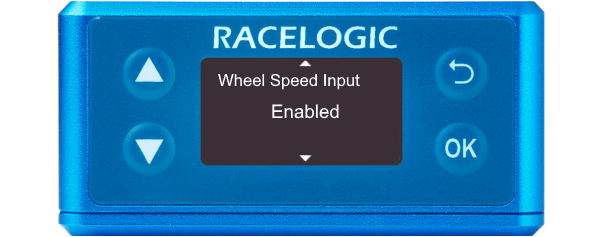
This setting allows wheel speeds to be passed into the Kalman Filter.
If the unit cannot detect CAN data, you will see a Warning Message on the front panel.
This action will add the Wheel Speeds channel to CAN ID 31D.
Notes:
- This option is only presented when the IMU integration is Enabled.
- If you want to configure the wheel speed further, you can do this in the VBOX Setup software.
IMPORTANT
Wheel speeds must not be used when conducting brake stops!
Note: This option is only presented when Wheel Speed Input is Enabled.
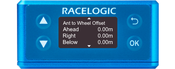
This setting specifies the X, Y, and Z distances between the antenna and the wheel speed reference point.
The reference point is the centre point between the rear wheels.
You can find more information here.
This setting specifies the X, Y, and Z distances between the antenna and the wheel speed reference point.
The reference point is the centre point between the rear wheels.
You can find more information here.
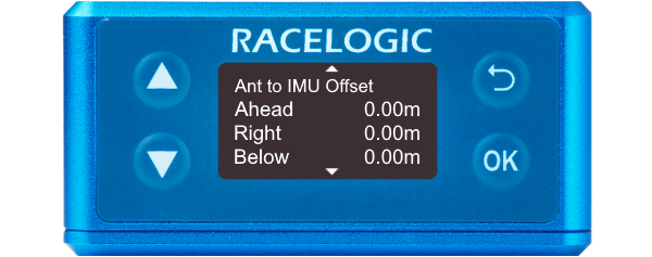
When Roof Mount is Disabled
Provides the X, Y, and Z offset values from the antenna to the Speed Sensor/IMU that is required for the Kalman Filter algorithm.
When Roof Mount is Enabled
Becomes Ant to Ref. Offset and provides the X, Y, and Z offset values from the roof-mounted IMU to the nominated reference point where all the measurements will be made.
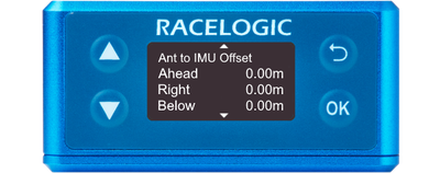
This is where you can add the X, Y, and Z offset values from the roof-mounted IMU to the nominated reference point where all measurements will be made.
When Roof Mount is Enabled:
This setting will become available and will automatically add a 1-metre Z-offset, to translate the filtered speed down into the vehicle towards the centre of gravity.

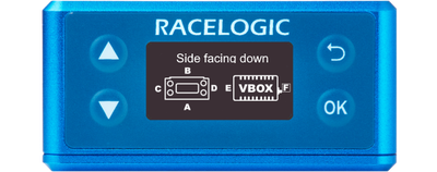
Select the orientation of the VBOX 3iS side facing down. This is only applied once the IMU menu is exited to the Main Menu. When the orientation is changed, the Kalman Filter is reset.
Note:
- This option is only presented when the IMU Location is set to ‘Internal’.
- If you use an invalid combination of sides facing down/forward, you will see an error message when you exit the IMU menu.
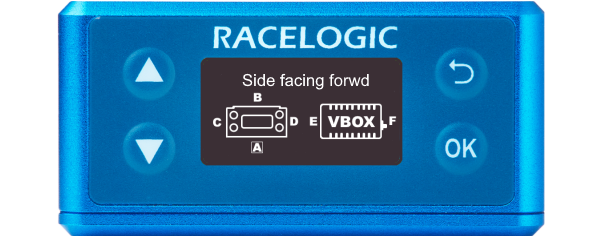
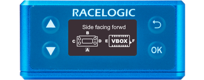
Select the orientation of the VBOX 3iS side facing forward. This is only applied once the IMU menu is exited to the Main Menu. When the orientation is changed, the Kalman Filter is reset.
Notes:
- This option is only presented when the IMU Location is set to ‘Internal’.
- If you use an invalid combination of sides facing down/forward, you will see an error message when you exit the IMU menu.
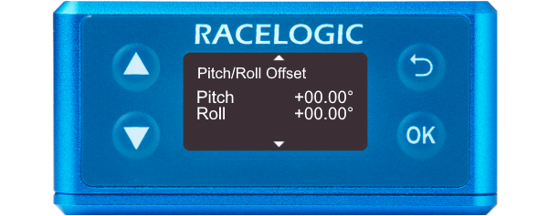
Auto Level
Begins the process of levelling the IMU calculated Pitch and Roll Angles. Once selected, the unit averages the pitch/roll angles over a 5-second period and will then subtract/add the averaged values to make the pitch/roll angle 0. This offset will be displayed on the main screen.
Clear
Clears the current pitch/roll offset values.
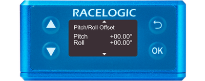
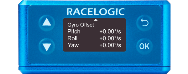
Auto Level
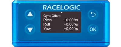
Begins the process of levelling the IMU calculated Pitch, Roll and Yaw Rates. Once selected, the unit averages the rates over a 5-second period and will then subtract/add the averaged values to make the rates equal to 0. These offsets will be displayed on the main screen.
If the IMU location is set to External and the unit cannot detect an external IMU, it will display an error message.
Clear
Clears the current offset values.
Auto Level
Begins the process of levelling the IMU calculated Pitch, Roll and Yaw Rates. Once selected, the unit averages the rates over a 5-second period and will then subtract/add the averaged values to make the rates equal to 0. These offsets will be displayed on the main screen.
If the IMU location is set to External and the unit cannot detect an external IMU, it will display an error message.
Clear
Clears the current offset values.