Please register your VBOX Speed Sensor unit so that Racelogic can continue to provide you with notifications about the latest software releases and firmware upgrades for your Racelogic product and offer technical support.
Register your device here.
| Product Code | Quantity | Description |
|---|---|---|
| VBSS100-V5 | 1 | VBOX 100 Hz GPS Speed Sensor unit |
| RLACS283 / RLACS324 | 1 | Dual Band GNSS Antenna (includes 4 m removable cable) |
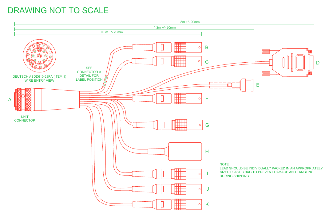
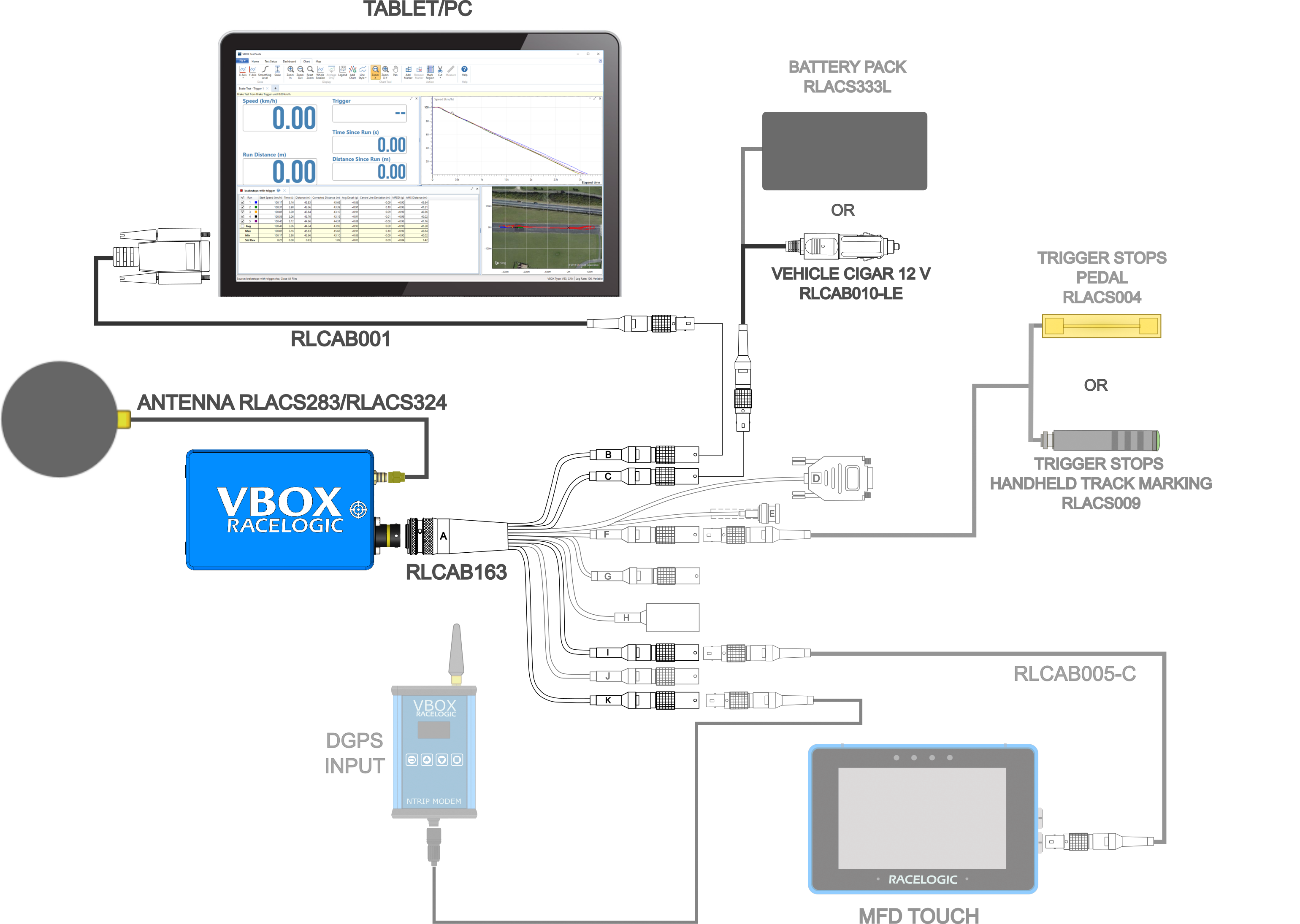
| RLCAB163 | 1 | Cable loom - Deutsch 23W ASDD - Multiple Connectors |
| RLCAB001 | 1 | Lemo 5W Plug - 9W Socket - 2 m (Serial Configuration) |
| RLACS106 | 1 | VBOX Plastic Carry Case |
| RLCAB010LE | 1 | Lemo 2W Plug - Cigar Plug - 2 m cable (Power) |
| RLCALUKAS | 1 | Certificate of Calibration |
Note: You may have to order additional cables separately.
VBOX 100 Hz Speed Sensor units are powered via the POWER IN lead or the CAN OUT + POWER lead on the supplied loom. You can use the RLCAB010LE cable to connect to a 12 V output point in a vehicle or you can use a battery pack.
IMPORTANT
- The maximum operating voltage input must not exceed 30 V DC. Failure to observe this could result in damage to the VBOX unit.
- The cable looms and unit connectors are colour coded. It is important that you use a loom with a colour marker that corresponds with the colour marker on the unit's connector. The VBOX 100 Hz GPS Speed Sensor (v5) has a yellow colour marker.
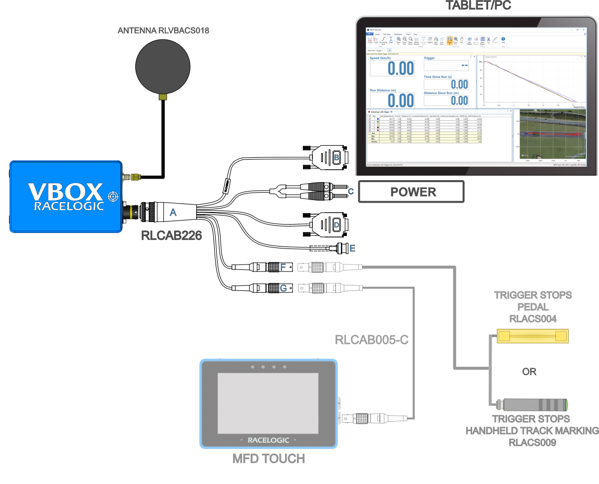
VBOX 25 Hz Speed Sensor units is powered via the POWER IN banana plugs. Alternatively, you can use the CAN OUT + POWER lead on the loom to pass power to the Speed Sensor from a third-party device. Contact Racelogic Support for further guidance.
IMPORTANT
- The maximum operating voltage input must not exceed 30 V DC. Failure to observe this could result in damage to the VBOX unit.
- The cable looms and unit connectors are colour coded. It is important that you use a loom with a colour marker that corresponds with the colour marker on the unit's connector. The VBOX 25 Hz GPS Speed Sensor (v2) has a yellow colour marker.
VBOX Speed Sensors have been designed to generate as little heat as possible and has a wide operating temperature range. It is, however, good practice to mount it in a position where it has sufficient airflow around the unit.
When installing a VBOX Speed Sensor in your vehicle, you can either fix it rigidly to the vehicle using the fixing holes or secure it with a telescopic mounting arm.
Try to position the unit as close to the centre of the vehicle as possible, and make sure that it is level with the ground.
Note: The VBOX unit and the antenna should be mounted on the same rigid body to provide a relative reference. So for a vehicle such as a truck cabin, both the VBOX unit and the antenna should be fitted to the cabin body (if the cabin is air-sprung) or to the vehicle chassis.
Note: It is important that you do not use force when connecting and disconnecting the loom to the VBOX unit.

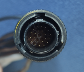
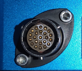

- Look at the connectors on both the loom and the unit.
- Locate the different-sized inner notches on the loom's connector and line them up with the equivalent notches on the unit's connector.
- Note the outer notches on the connector.


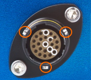
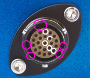

Push the connectors gently together and twist the outer ring on the loom's connector until it slots in place and locks the connection.
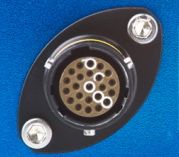
Note the notches on the connectors as illustrated above. Twist the loom's connector while you gently pull it away from the unit.
You can find more details about how to mount and connect your VBOX Speed Sensor and antenna in the complete User Guide.
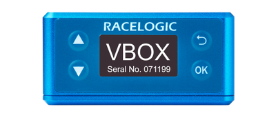
When the VBOX Speed Sensor is powered up, it will display the RACELOGIC logo along with hardware variant and the serial number of the unit. Next, it will change to display the firmware version of the unit.
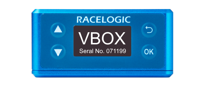
When the VBOX Speed Sensor is powered up, it will display the RACELOGIC logo along with hardware variant and the serial number of the unit. Next, it will change to display the firmware version of the unit.
When the unit has initialised and any warnings have been cleared, the number of satellites will be displayed.
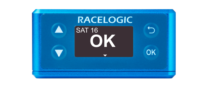
When the unit has initialised and any warnings have been cleared, the number of satellites will be displayed.
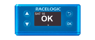
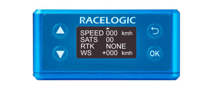
Press the Down arrow to open the status screen where you can view information about Speed, Satellite count, RTK Status and Wheel Speed.
Press the Up arrow to return to the main screen.
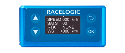
Press the Down arrow to open the status screen where you can view information about Speed, Satellite count, RTK Status and Wheel Speed.
Press the Up arrow to return to the main screen.
Model Limitations
- Wheel speed is not supported on the VBOX 100 Hz Speed Sensor (v5).
- RTK and wheel speed is not supported on the VBOX 25 Hz Speed Sensor (v2)
Non-supported values on the Status screen will be zeroes.
This is a general overview of the VBOX Setup software, connected to a VBOX Speed Sensor, and its functionality. You can use the VBOX Setup Software to configure your VBOX unit. It provides greater functionality in comparison to using the Front Panel.
To configure a VBOX Speed Sensor unit, it needs to be connected to a power source and a computer.
Configuration is performed using VBOX Setup Software, which can be downloaded here. Using the supplied loom, connect an RLCAB001 cable to the SERIAL lead and connect the serial plug to the computer's serial port – this can be done via a serial > USB converter if required.
IMPORTANT
Microsoft Windows 7 SP1 or newer is required (must be compatible with .Net Framework 4.7.1)
Once physically connected and powered, open the software and use the drop-down list to select the correct COM port that your VBOX unit is connected to. VBOX Setup automatically connects to the selected device and enters the setup screen for your unit.
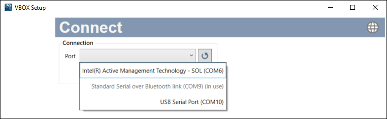
Note: An auto-detect message may appear if the baud rate has been changed from the default value - select ‘Yes’ to allow the different baud rates to be scanned.
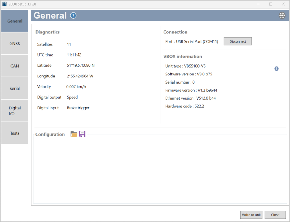
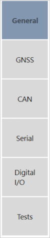
The menu buttons in the sidebar allows you to navigate between the different settings menus. Click the buttons to select the desired menu.
The menu buttons in the sidebar allows you to navigate between the different settings menus. Click the buttons to select the desired menu.

Clicking on the question mark icon when you have an active internet connection will open the corresponding user guide page for the menu within the Racelogic Support Centre.
Clicking on the question mark icon when you have an active internet connection will open the corresponding user guide page for the menu within the Racelogic Support Centre.
The header displays the name of the menu that you have currently selected.

The header displays the name of the menu that you have currently selected.

By clicking the globe icon, you can select the language that VBOX Setup uses.

By clicking the globe icon, you can select the language that VBOX Setup uses.

This is the main area of the screen that will show relevant settings and information.
After making changes to your setup, the Write to Unit button should be selected to ensure the settings have been uploaded to the connected VBOX Speed Sensor.
After making changes to your setup, the Write to Unit button should be selected to ensure the settings have been uploaded to the connected VBOX Speed Sensor.

Clicking this button closes the software. You will be prompted to save the settings if the changes have not been written to the VBOX Speed Sensor unit.

Clicking this button closes the software. You will be prompted to save the settings if the changes have not been written to the VBOX Speed Sensor unit.

The sidebar enables you to switch between the different settings menus; General, GNSS, CAN, Serial, Digital I/O and Tests.
Click on the menus below to view more information.