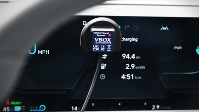
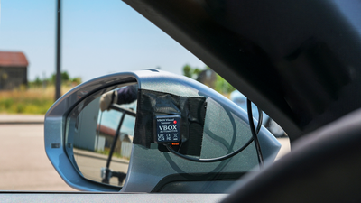
When you are mounting the Visual Sensor, you can choose the mounting method that best suits your testing scenario. It is, however, important to make sure that the light source you wish to test is the only light hitting the sensor during the test. To stop bleeding light from entering the sensor, we are supplying padded stickers for the bottom of the sensor, including some with double-sided tape for easy mounting.
If you are mounting the sensor on an uneven or rounded surface, you may wish to apply dark tape around the edges to stop light from bleeding through and reaching the sensor.
NOTE
The padded stickers have holes in them. When you are applying the padded sticker to the bottom of the sensor, you must make sure that the hole is aligned with the actual sensor.
| Wire Colour | Function |
|---|---|
| Red | Power |
| Green or Black* | Ground |
| Yellow | Signal Ground |
| Blue | Signal |
*Depending on hardware version.
- Wire the green/black wire to the ground pin (15).
- Wire the red wire to the power pin (9).
- Wire the yellow wire to a negative pin in an available Isolated Channel pair.
- Wire the blue wire to a positive pin in an available Isolated Channel pair.
In this example we are using channel 4 for the signal wires.
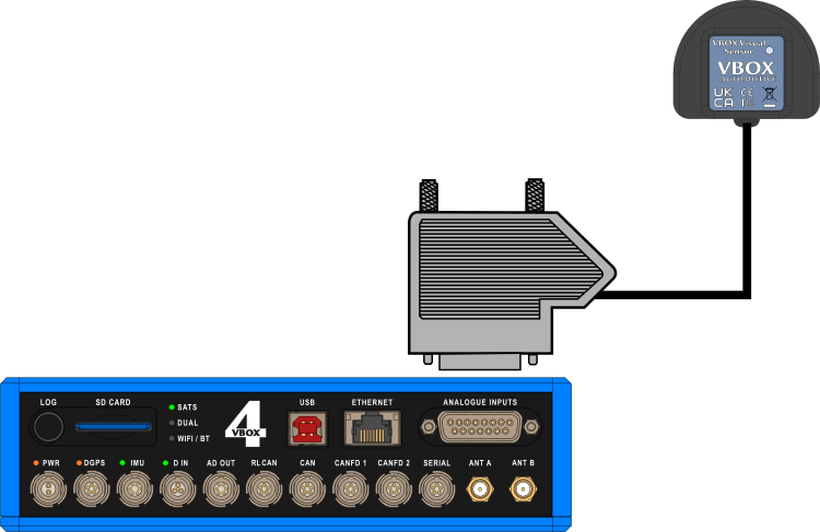
You can find the pin information for the analogue Input connector on VBOX 4 here.

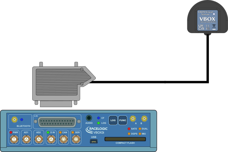
- Wire the green/black wire to the ground pin (15).
- Wire the red wire to the power pin (9).
- Wire the yellow wire to a negative pin in an available Isolated Channel pair.
- Wire the blue wire to a positive pin in an available Isolated Channel pair.
In this example we are using channel 4 for the signal wires.
You can find the pin information for the analogue Input connector on VBOX 4 here.

NOTE
Take note of the channel you are connecting the signal wires to, as you will need to configure this channel in the Channel Setup menu in the VBOX Setup software when you connect the sensor to the VBOX.
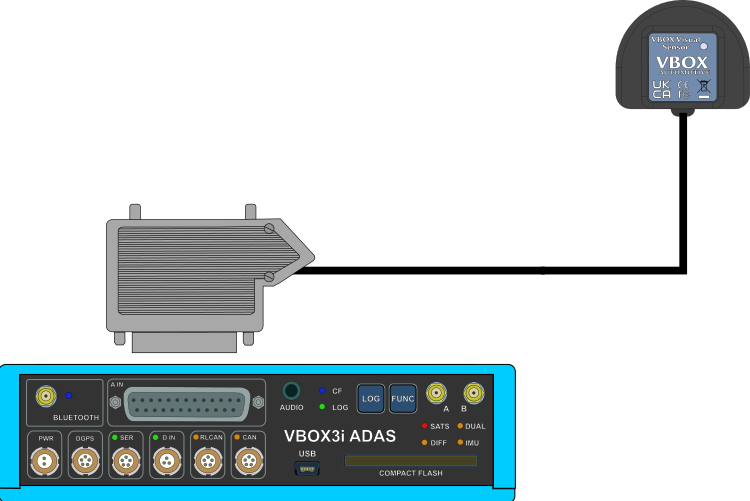
- Wire the green/black wire to the ground pin (15).
- Wire the red wire to the power pin (14).
- Wire the yellow wire to a negative pin in an available Isolated Channel pair.
- Wire the blue wire to a positive pin in an available Isolated Channel pair.
In this example we are using channel 1 for the signal wires.
You can find the pin information for the analogue Input connector on VBOX 3i ADAS here.

NOTE
Take note of the channel you are connecting the signal wires to, as you will need to configure this channel in the Channel Setup menu in the VBOX Setup software when you connect the sensor to the VBOX.