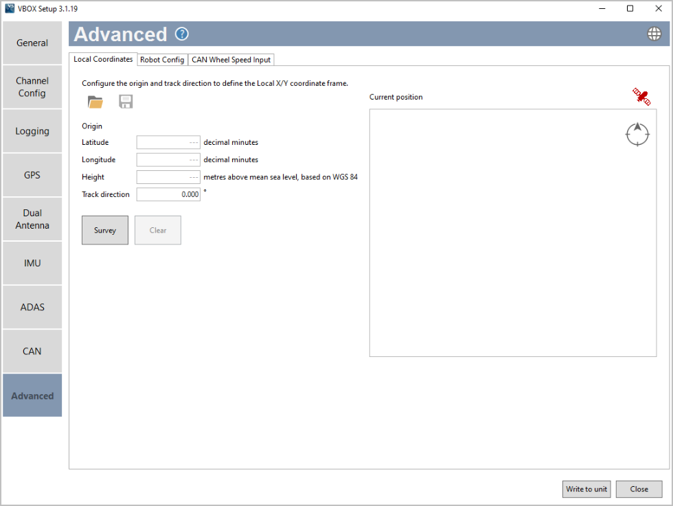
The Local Coordinates tab in the Advanced menu is there for you to survey and see the local co-ordinate frame (X and Y position) used for the channel calculations.
You will be able to:
- See the location of the local co-ordinate frame datum point.
- See the track heading, relative to the datum point.
- See the position of the subject vehicle relative to the local coordinate frame.
- Save a .VBC file.
- Load a .VBC file.
You can survey the origin, track direction, and coordinates. Click Survey to set the coordinates to the location of the antenna for your VBOX 3i ADAS unit.
Clear an already surveyed location.
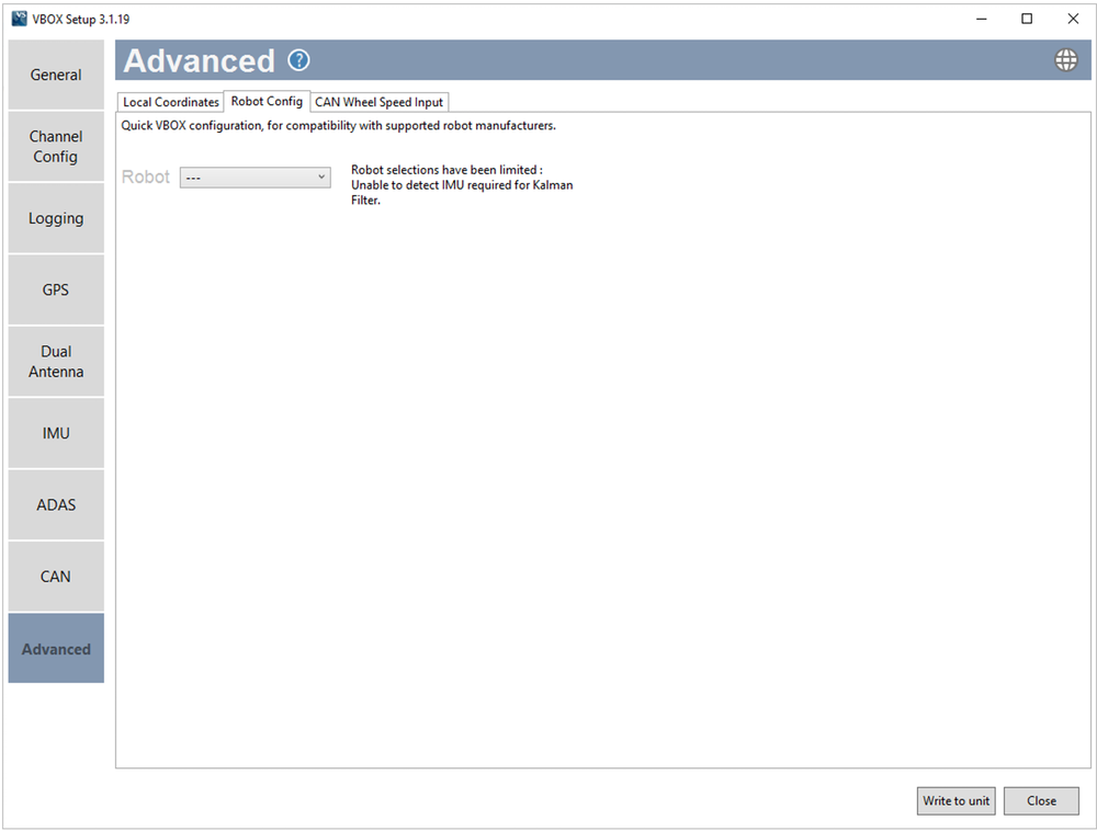
Configure VBOX 3i ADAS to integrate with supported third-party robots. You will be able to select options based on compatibility with your connected hardware, such as integrated IMUs.
Note: By enabling a robot mode, the VBOX 3i ADAS unit will expect certain settings.
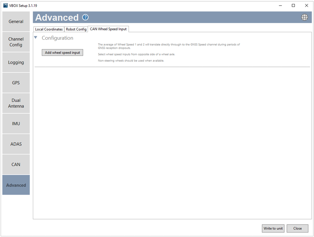
Configure the CAN Wheel Speed Input by adding the channels you wish to use.
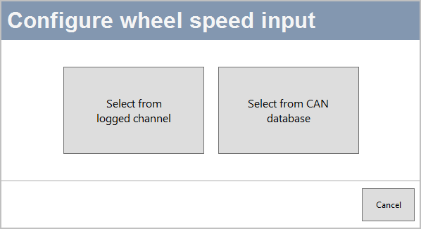
You can set the wheel speed inputs with an already configured CAN input channel.
You can select channels for wheel speed from the internal database or from a database file.
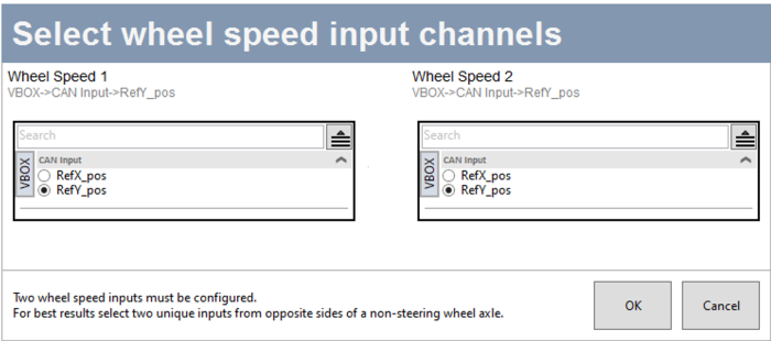
Click the Add wheel speed input button to open the Select wheel speed input channels window and set your input channels.
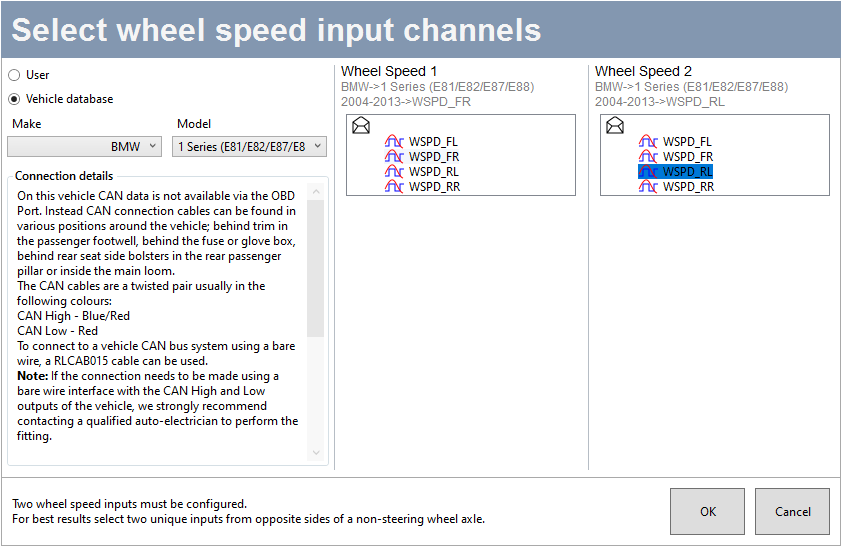
- Select the User radio button to choose wheel speed input channels from a user-configured database file.
- Select the Vehicle database button to choose wheel speed input channels from the internal vehicle database.
- Make – Use the dropdown menu to see a list of available makes and select the one that applies to your setup.
- Model – Use the dropdown menu to see a list of all available models and select the one that applies to your setup.
The Connection details area will provide you with available CAN connection information for the selected vehicle.
The Wheel Speed 1 and 2 sections will display lists of available options for Wheel Speed 1 and 2, based on your selection in the vehicle database or your database file.
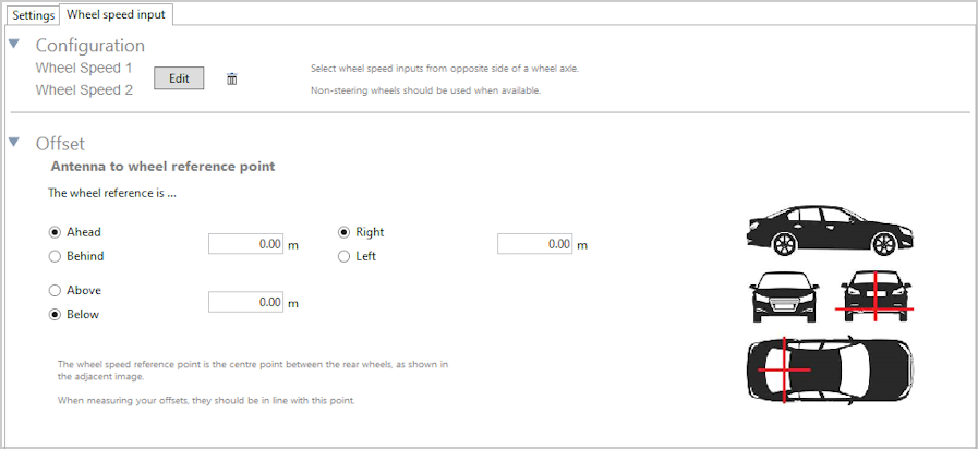
After configuring your wheel speed inputs, you must measure and enter the offset from the antenna to the wheel reference point. The Wheel speed reference point is the centre point between the rear wheels. Make sure that your measurements are in line with this point.