The following report describes the testing performed to characterise the accuracy of the FIXED delay function of the VBOX Automotive Audio sensor shown in Figure 1 below:
The decision to review a fixed delay to the output was taken following initial testing on the native output of the ADAS Audio Sensor. This testing showed an internal detection time fluctuating between 70 to 90 ms (although subsequent assessments, as recorded in this report, have shown a fluctuation of 80 to 96 ms). To eliminate the variability of the unit, we developed a function where the user can offset this delay, essentially absorbing any internal variable delays in this fixed period. The following is a test on the accuracy of the delay at differing values of fixed delay.
We created a simple circuit with a push-to-connect switch to trigger a 2.3 kHz piezo buzzer on or off. This circuit was connected to the D IN port of the VBOX to attain a highly accurate ‘ON’ signal when the buzzer was activated. Additionally, the VBOX audio sensor was set to trigger on the 2.3 kHz frequency of the buzzer and the output from the audio sensor was connected to the digital input to the VBOX.
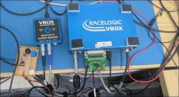
To characterise any delay in the time that the buzzer takes to create a signal, an initial test set-up was created with a microphone circuit connected to the oscilloscope adjusted to detect the 2.3 kHz signal being present at the microphone.
- Channel 1 of the oscilloscope was connected to the switch feed to the buzzer, and the oscilloscope trigger was set to capture the rising edge of this ’ON’ signal as the T zero point.
- Channel 2 of the oscilloscope was connected to the digital output of the Audio sensor.
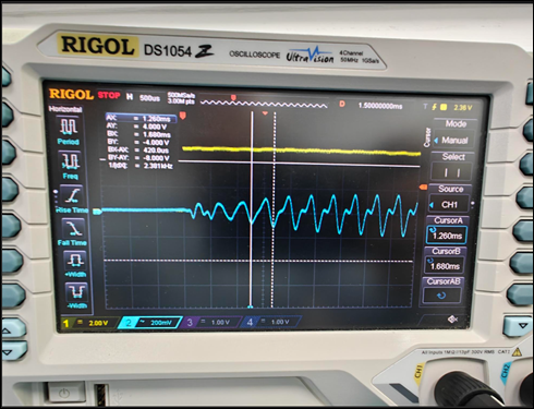
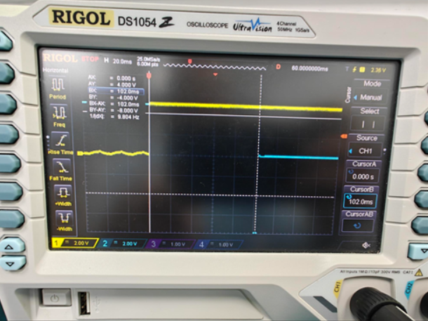
The first test was to confirm that the signal present on Channel 2 is the 2.3 kHz signal being received by the microphone. Using the oscilloscope cursor function, this was confirmed, as shown in Figure 3.
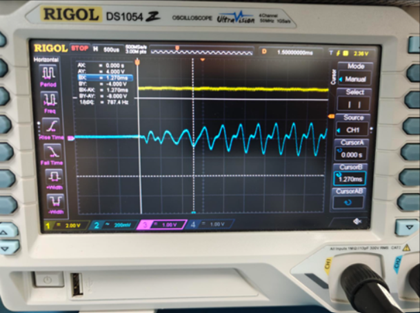
The cursor was then adjusted to the time from the start of the electrical signal to the first sign of a 2.3 kHz sound at the microphone. This is shown in Figure 4 below and confirmed as being approximately 1.0 to 1.3 ms.
In order to reliably and reproducibly assess the accuracy of the 100ms user added delay, a test was repeated 15 times where the buzzer was activated and the time from signal start to Audio sensor detection measured on the oscilloscope. The results were recorded in a spreadsheet and summarised in the Results section below.
This process was then repeated for user defined fixed delays of 120ms, 140ms, 160ms and 180ms and tabulated within the Results section.
| Fixed Delay | ||||||
|---|---|---|---|---|---|---|
| 0 ms (Native accuracy of Audio Sensor) | 100 ms | 120 ms | 140 ms | 160 ms | 180 ms | |
| 81 | 100 | 120 | 141 | 165 | 181 | |
| 81 | 105 | 126 | 142 | 162 | 183 | |
| 94 | 102 | 125 | 143 | 157 | 186 | |
| 86 | 99 | 118 | 140 | 158 | 181 | |
| 92 | 105 | 119 | 138 | 164 | 181 | |
| 84 | 104 | 118 | 140 | 164 | 183 | |
| 96 | 101 | 124 | 142 | 158 | 178 | |
| 85 | 99 | 120 | 142 | 160 | 185 | |
| 92 | 102 | 120 | 143 | 160 | 178 | |
| 90 | 101 | 122 | 143 | 161 | 178 | |
| 80 | 98 | 120 | 144 | 162 | 180 | |
| 84 | 102 | 120 | 144 | 160 | 182 | |
| X | 101 | 120 | 140 | 160 | 182 | |
| X | 99 | 127 | 144 | 161 | 182 | |
| X | 101 | 123 | 138 | 161 | 181 | |
| Average | 87.08 | 101.27 | 121.47 | 141.60 | 160.87 | 181.40 |
| Average minus system offset of 1.2 ms | 85.88 | 100.07 | 120.27 | 140.40 | 159.67 | 180.20 |
| Standard dev. | 5.50 | 2.15 | 2.88 | 2.03 | 2.29 | 2.3 |
| Average standard dev. | x | 2.26 | ||||
The table includes the nominal system offset of 1.2 ms. This is the time taken for the buzzer to create a sound after ‘On’ signal and is described in the ‘Test Preparation - System offset test’ above.
Once this internal system delay is removed from the results, it can be seen that the audio sensor is outputting the signal with a worst-case accuracy of 2.88 ms (1σ).
A sensor of any type takes a certain amount of processing time to complete its action. This is also the case with the VBOX Audio Sensor to confirm a user-specified frequency. This can be seen within the 0 ms assessment results, where the accurately recorded latency is between 80 ms to 96 ms. This amount is variable but calculable.
The VBOX Automotive Audio Sensor outputs in two ways:
- Digital output: For output to the digital trigger on a VBOX or into any other third-party logger.
- CAN output: Read as a CAN module in the VBOX for automated message configuration.
As discussed in the sections above, the delay can be offset by a fixed output when using the digital output for improved accuracy.
The CAN output is treated differently; the CAN message contains the calculated signal delay of each detection as part of its message. Therefore, rather than adding a fixed delay at source and then removing it within the test suite calculation, it is possible to attain the absolute delay for each activation and directly adjust it from the online or offline posted results.
Setup was similar to the digital delay output, a buzzer was connected to the D IN port of the VBOX to attain a highly accurate ‘ON’ signal, and the Audio Sensor was set to trigger upon the 2.3 kHz frequency of the buzzer.

A test was then developed within test suite to start on the ‘Trigger ON’ state of the buzzer (i.e. the highly accurate D IN trigger). The test was then set to end when the ‘Trigger Status’ CAN message is detected as on. Given that the system offset is constant and known (1.2ms) and the calculated CAN delay is outputted as part of the CAN message, it is possible to assess the overall error as shown in Table 2 in the results section below.
| Time (ms) | Calc. Delay (ms) | Detect Time Difference (ms) (inc 1.2 ms system offset) | |
|---|---|---|---|
| 107.7 | 108.535 | -1.985 | |
| 100.1 | 104.334 | -5.414 | |
| 106.2 | 107.324 | -2.304 | |
| 92.7 | 92.988 | -1.458 | |
| 112.1 | 111.233 | -0.373 | |
| 107.7 | 108.648 | -2.108 | |
| 101 | 104.867 | -5.057 | |
| 110.1 | 111.82 | -2.97 | |
| 116.4 | 115.858 | -0.648 | |
| 116.6 | 116.303 | -0.913 | |
| 97.2 | 101.233 | -5.273 | |
| 113 | 112.947 | -1.167 | |
| 113.8 | 114.356 | -1.786 | |
| 114.5 | 115.301 | -2.001 | |
| Avg | - | - | -2.38979 |
| Max | - | - | -0.373 |
| Min | - | - | -5.414 |
| Std Dev | - | - | 1.69436 |
When making use of the calculated signal delay CAN message, the audio sensor is outputting a trigger with accuracy of 1.69 ms (1σ).