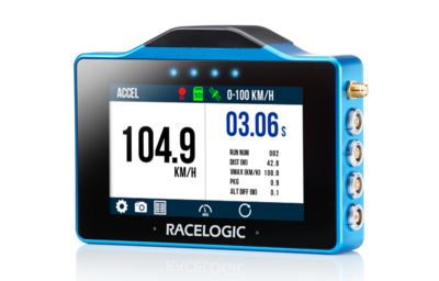
This page contains an overview of the VBOX Touch hardware. It will show the unit and explain the connectors and LEDs.
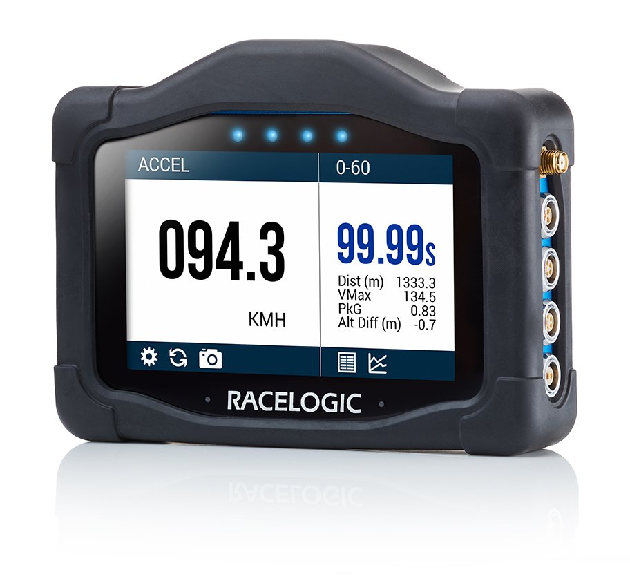
VBOX Touch is a data logging device. It features an integrated touchscreen interface that is used to navigate menus, control logging, and view results.
The unit contains internal GNSS capability and supports connection to an external antenna for improved performance.
This page contains an overview of the VBOX Touch hardware. It will show the unit and explain the connectors and LEDs.
VBOX Touch is a data logging device. It features an integrated touchscreen interface that is used to navigate menus, control logging, and view results.
The unit contains internal GNSS capability and supports connection to an external antenna for improved performance.
The internal GNSS antenna provides positional and speed data to the unit.
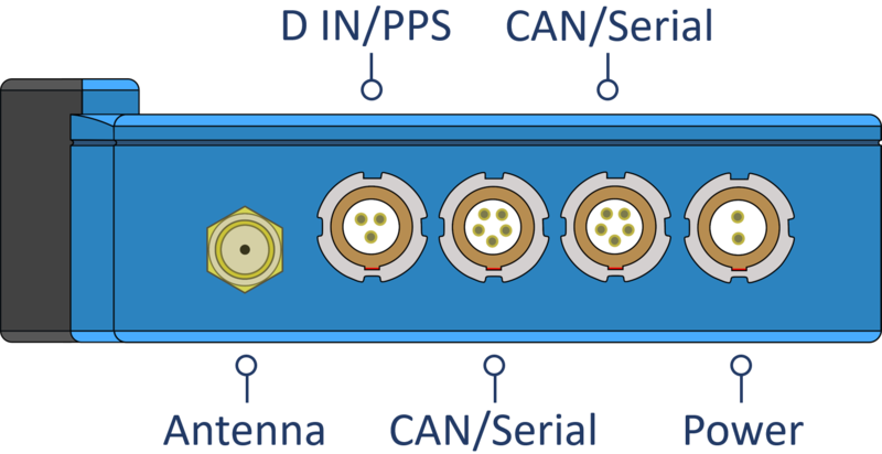
Refer to the VBOX Touch Pinouts page for more detailed connector information.
If you are struggling to maintain a stable satellite lock using only the internal GNSS antenna, you can connect the supplied external GNSS antenna to the antenna port.
The external antenna should always be used when VBOX Touch is logging Brake Trigger Tests.
The Digital In and PPS port can be used to connect a VBOX Brake Pedal Trigger when performing brake trigger deceleration tests.
The port can also be used to connect a Handheld Start/Stop Logging Switch (RLVBACS010) to control the logging on the unit.
The top CAN/Serial port can be used for both CAN data and Serial connection.
CAN
Receive and transmit data via CAN.
Refer to the Configuration page for more information.
Serial
Output serial information, allowing you to either:
- Connect VBOX Touch to VBOX Test Suite (using an RLCAB001 cable) to conduct live testing.
- Output lap timing parameters.
The bottom CAN/Serial port can be used for both CAN data and Serial connection.
CAN
The bottom CAN/Serial port can be used receive and transmit data via CAN.
Refer to the Configuration page for more information.
Serial
VBOX Touch RTK units can also use the bottom CAN/Serial port to receive RTK corrections from an NTRIP Modem or a Telemetry Radio Module with a Static Base Station.
VARIANT LIMITATION
Only VBOX Touch RTK units can use the bottom CAN/Serial port for Serial connection. The port will not be available for configuration in the Serial Port Settings on VBTOUCH-V2 and VBTOUCH-V3.
The power port is used to connect the VBOX Touch to a vehicle power supply.
The unit requires a stable power connection to operate and record data during testing.
The unit powers on automatically when connected to a power source.
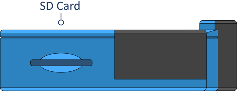
The SD card slot on the left side panel of the unit is used to insert the SD card, where all logged data is recorded and saved.
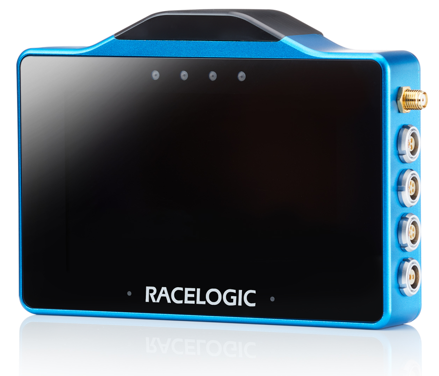
VBOX Touch has 4 LEDs above the display. These LEDs are contextual feedback indicators tied to system state, user actions, and test behaviour, and they can flash in different colours and different frequency patterns depending on the process the unit is performing.
Refer to the User Interface page for more details about the different LED behaviours.
A protective rubber cover is supplied to help protect the unit during use and to improve handling.