- Make a connection to the vehicle to log RPM, either through CAN or using an Input Module.
- Log a data file that contains speed and RPM, incrementing through all gears without skipping any:-
1, 2, 3, 4, 5 – etc. This does not need to be done at high speed.
Range values
Load the data file into either Performance Tools software. This is installed with Video VBOX Setup software and will be located in:
Start → All Programs → Racelogic → Performance Tools
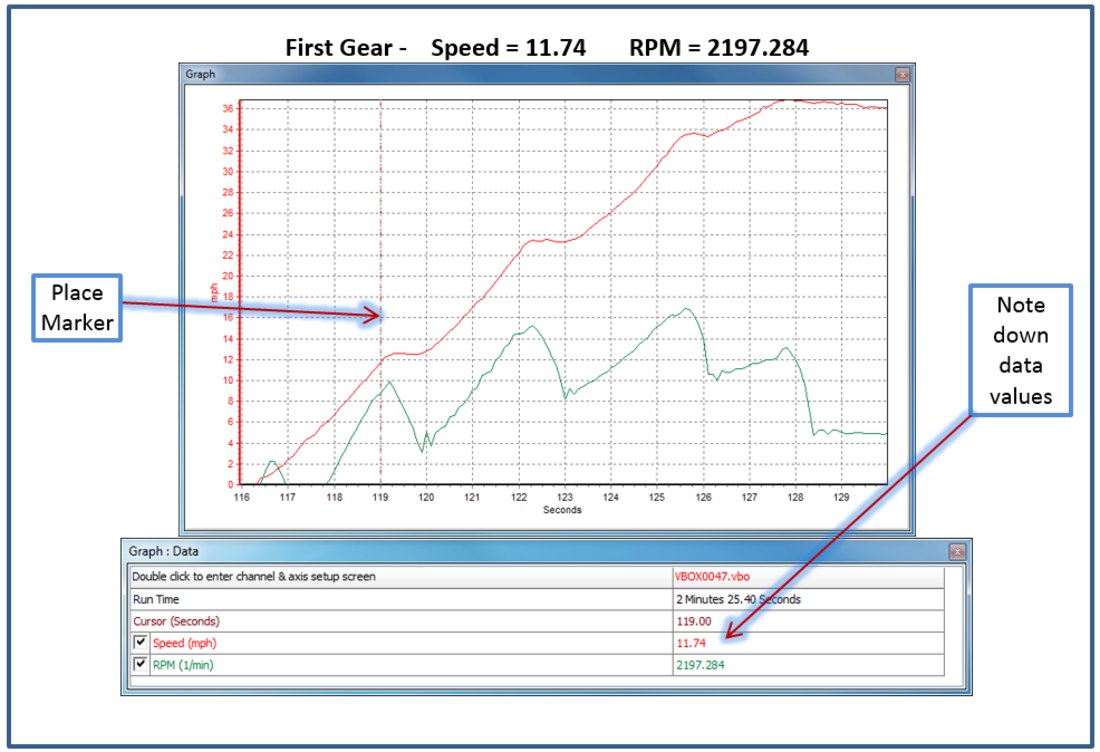
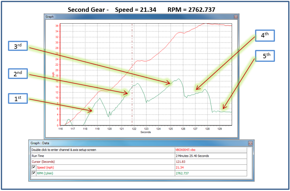
Pick a point in each gear and write down the speed and RPM values shown in the ‘Graph: Data’ window – you can see the gear changes in steps.
NOTE
Make sure that the software is using the correct speed units (MPH/KPH) for your application.
You can see my example data file in the images below; these are showing data being picked from gears 1 and 2.
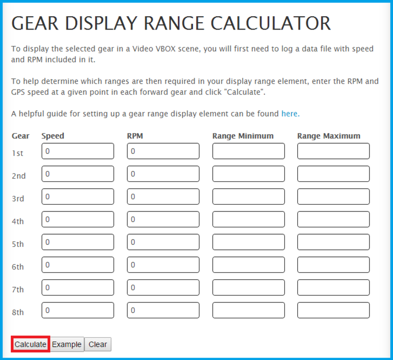
When you have noted down the speed and RPM from each gear range, input these values into the ‘Gear Display Range calculator’
This calculator will work with any speed units, but you must be consistent and use the same units throughout.
Once you have added all your values in, hit the calculate button. You should now see a list of minimum and maximum number ranges. Note these values down so that they can be added into Video VBOX Setup software.
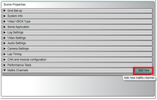
In Video VBOX Setup software, you must create a maths channel for ‘Speed÷RPM’.
To do this, simply click the ‘Add New’ button in the Maths Channel section under Scene properties.
A ‘Maths Channel Setup’ window will then appear – here is where you must enter the equation ‘Speed ÷ RPM’ using the corresponding channel buttons.
You should also name the maths channel – e.g. ‘Speed RPM’
NOTE
Make sure the speed units are set to the correct type for your application.
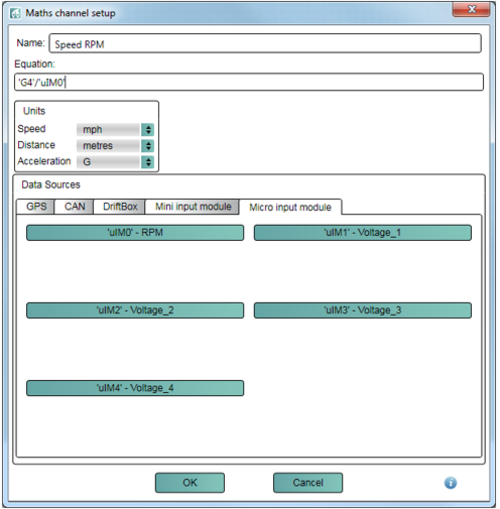
When you have entered this equation, click ‘OK’. The maths channel will now appear under scene properties
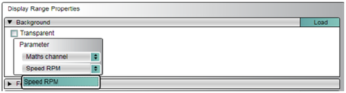
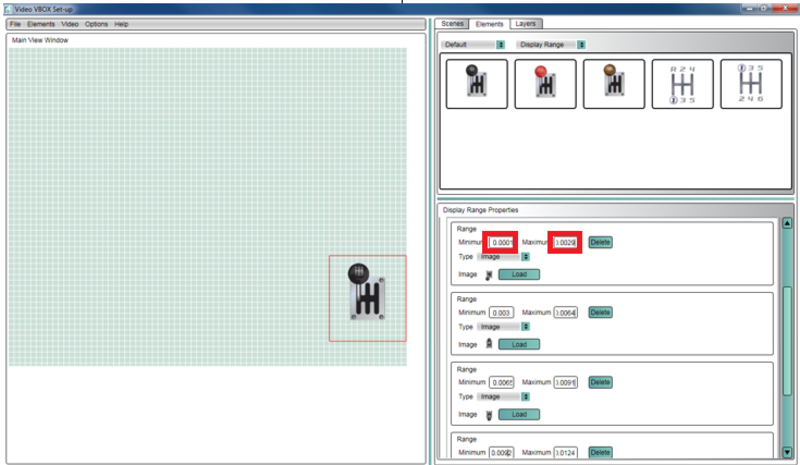
Then, drag one of the pre-configured ‘display range’ elements into your scene.
You should set the parameter to Maths channel/ Speed RPM (or as named).
Next, you should set the minimum and maximum for each gear range to the same values as reported in the calculator on the website.
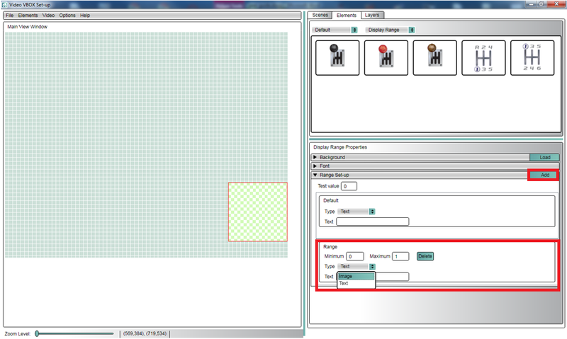
If you wish to set up your own display range element, you should select ‘Elements/New/Display Range’ from the top left menu bar. You will have to click ‘add’ for the correct number of ranges you require.
You must then load in an image, or set the text you wish to be associated with each range - and set the maximum and minimum values.
When you are happy all of the ranges are set up correctly, upload the scene file to your Video VBOX Unit.
The display range element should now work as a gear indicator for your vehicle!
NOTE
If you change to a different make or model of car, this process will need to be done again.