Description
How to remove and refit the ribbon cable within a VBOX Mini, DriftBox or PerformanceBox.
Background
These steps detail the procedure to either reset the GPS engine or check for intermittent connection to the display screen. These instructions can be passed to the customer to try before a unit is sent back to us.
IMPORTANT
- These instructions are to be followed at the customers own risk. This procedure should be followed through in a clear working area on a non-conductive surface.
- Racelogic accepts no responsibility for any damage caused to equipment.
This may be rectified by removing and refitting the ribbon cable within the unit, please follow the steps below:
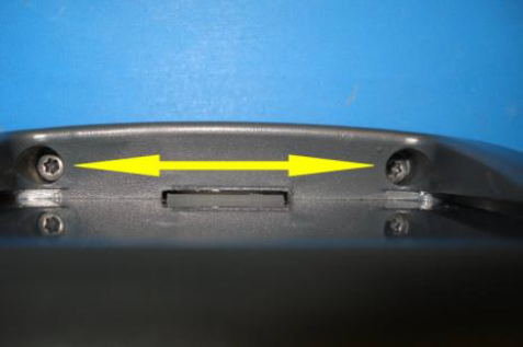
- Remove the four screws securing the front panel to the rear casing.
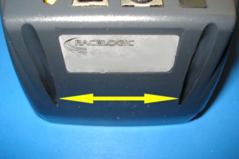


- The front panel and rear casing will now come apart; carefully move them in opposite directions supporting the PCBs and preventing excessive ribbon cable movement as they come out.
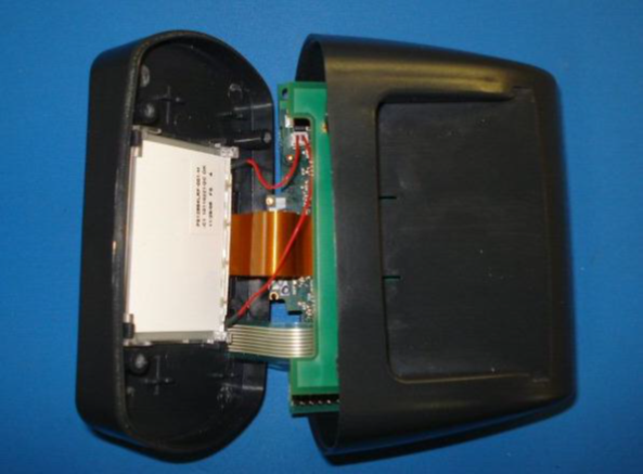
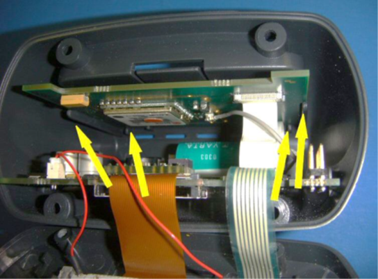
- The rear casing can now be taken away from the remaining parts and then the PCBs can be laid out as per the picture below.
- Make a note of the locations, positions and orientation of all the cables.
- Connect power to the unit.
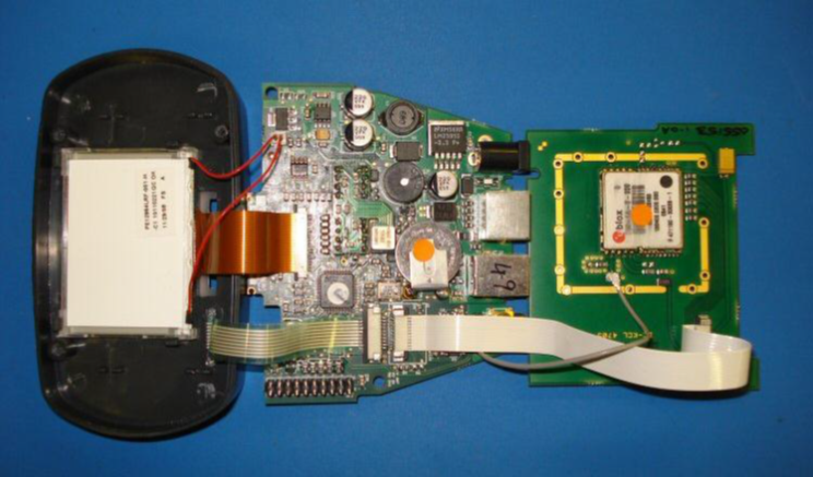
- Locate the white ribbon cable that goes from the main PCB to the GPS PCB.
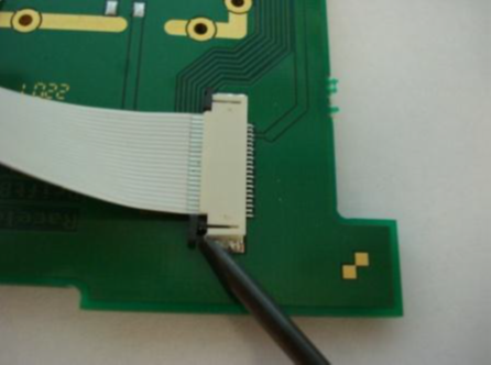
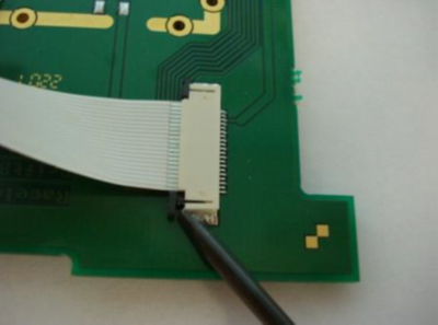
- With the power still connected, one side of the white ribbon cable needs to be disconnected (it doesn’t matter which side). Using a small flat blade screwdriver push the small black tabs out on one side of the connector then the other, you will have to repeat this a few times until both sides of the ribbon cable can be disconnected. Be very careful doing this as the tabs and cable are delicate.

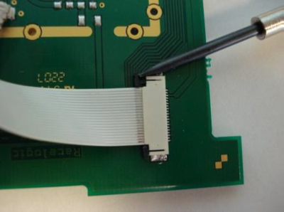
When the cable is re-connected, make sure the ribbon is as far into the connector as it can be, then use the flat blade screwdriver to push down the tabs. The unit should then ‘bleep’ and reset.
- The screen should now be showing the normal power up display.
IMPORTANT
Carry out a GPS cold start. This can be done through by selecting MENU > SETUP > COLDSTART. Wait for it to complete this process. Exit the menu and power down the unit.
- Pull the GPS PCB over the top of the main PCB and carefully slide the main PCB into the rear case moulding.
- Slide the GPS board into the top of the rear casing. Making sure it is located in the 4 slots, 2 nearest the front and 2 at the rear.
- Fit the front moulding to the rear, making sure the LCD flexi is above 12. the main PCB. Screw the two case halves together with the 4 self-tapping screws, taking care not to over-tighten them. Shake the unit, if you hear something moving this is most likely the GPS engine not being fitted into the slots correctly.
- Power the unit then enter the GPS diagnostics screen via the menu system.
- All of the fields will initially show zeros with the exception of the Tim(e) field which will be counting up in seconds since the unit was powered.
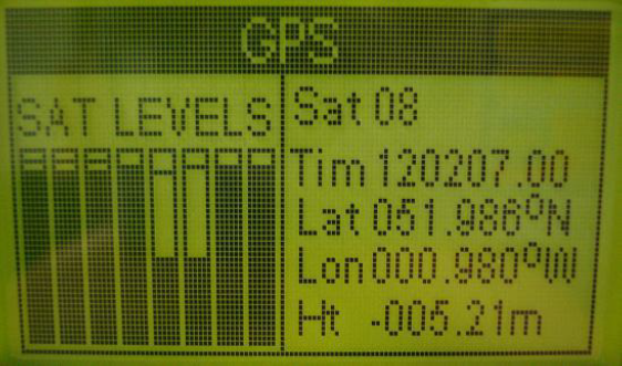
- The ‘Tim’ field will normally show the UTC Time within approximately 20 seconds.
- The ‘Lat’ and ‘Lon’ fields will normally show a position within approximately 50 seconds.
- Ensure that the ‘Sat’ field shows a satellite count of 5 or more within approximately 60 seconds of the unit having been powered. This confirms that the GPS engine has been connected and operates correctly. Disconnect the power from the unit.