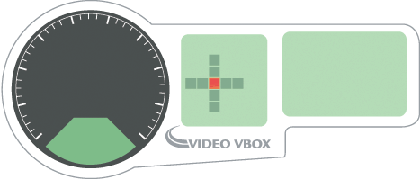
A gauge can be any shape, but is typically circular with a rotating needle.
Gauges can be used to display any of the available GPS or CAN/input module parameters such as speed (GPS), RPM (CAN/module) etc.
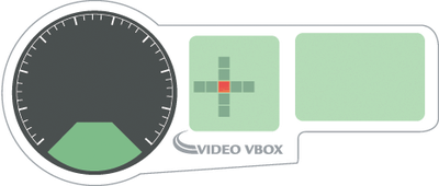
There are a number of preconfigured gauges which have different ranges and styles which can be inserted into the scene by dragging and dropping.
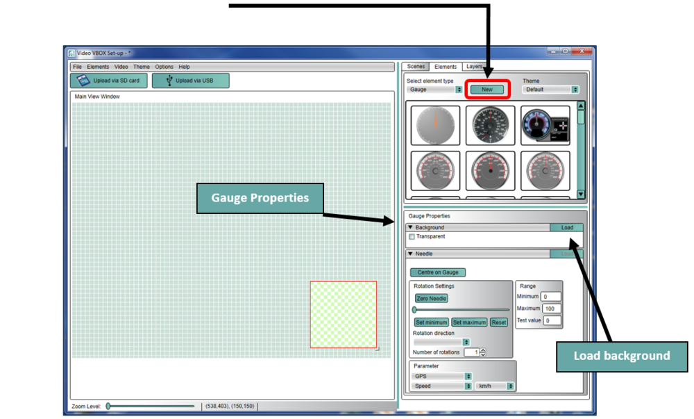
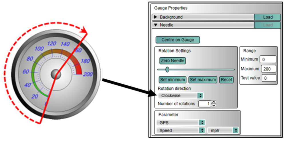
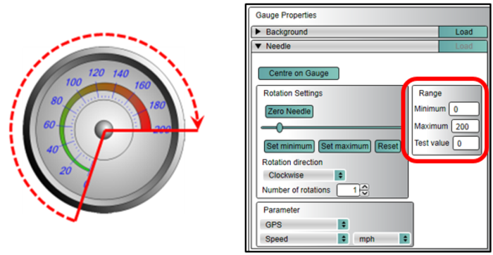
You then need to configure the parameter which is displayed, and the units using the Gauge Properties section (highlighted).
Select the Elements Tab on the right hand side.
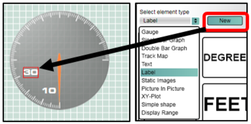
Select Gauge, then use the New button.
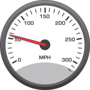
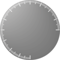
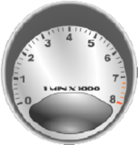
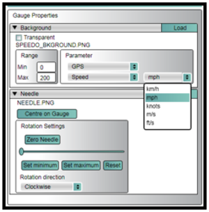
The background of the gauge is the face of the element, it can be a .bmp, .jpg or .png file. It can contain the numbers for the gauge, or it could be blank, with the numbers being added in afterwards. Examples below.


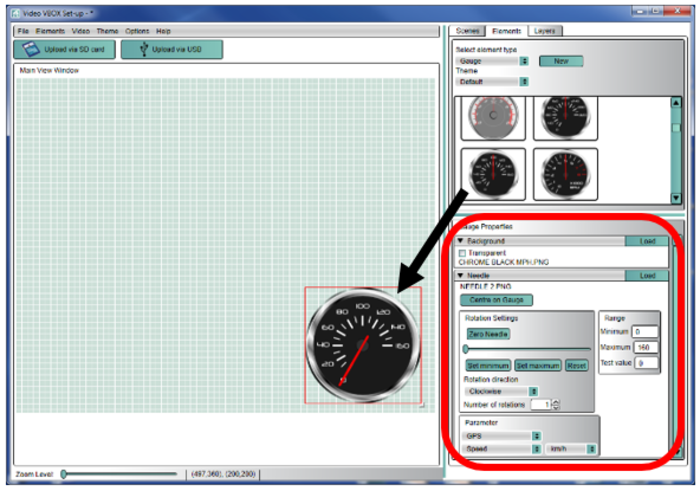
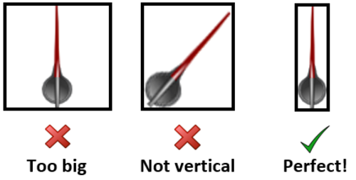
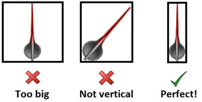
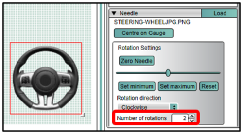
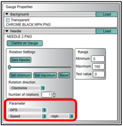
Once a background has been selected, you can now load a needle. The needle is a simple vertical image of a needle and must not have any spare space or borders around the image.

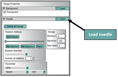
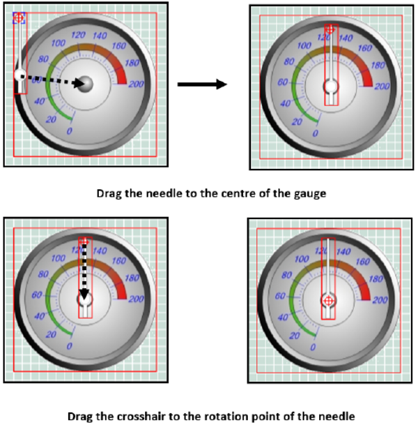
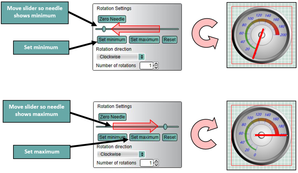
If multiple rotations of the needle are required, enter the number of full rotations required here. If partial rotations are required, the Set Minimum and Set Maximum function can be used.
The most flexible gauge to use is a blank gauge without any numbers. To use this element, just drag and drop this gauge from the Elements tab onto your scene. Then you can add the speed labels around the gauge using the Label element type.
The speed range does not have to start from zero, it can go from 25 to 125 for example, but make sure you set the Min (25) Max (125) range under Background for this element. Note that the needle will always be drawn over the top of any other element.
Set the maximum and minimum values to match the face of the gauge. Note you do not have to start at zero.
You can use any logged parameter to display on the gauge, select from the menu under Gauge Properties.
You can change the units of the parameter using the drop down menu shown below.
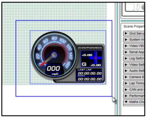
By clicking and dragging a selection box around a number of elements you can create a temporary group, which can then be dragged anywhere on the scene as one item. You can also copy and delete multiple items using this method, just right click over the grouped elements to bring up a menu of functions.