As well as having the ability to adjust settings within the HD2 unit, VBOX Video Setup Software provides full graphical overlay user configurability. For example, you can create custom dials, choose how large/ where you would like your logo to be and also change where the second camera is located. The scene can then be uploaded on to the unit by saving to an SD card or USB memory and inserting into the powered VBOX.
VBOX Video HD2 Setup Software (Windows) can be downloaded here.
IMPORTANT
Microsoft Windows 7 SP1 and VBOX Video HD2 Firmware version V1.3.72 or newer is required.
The main areas of the software are shown below:
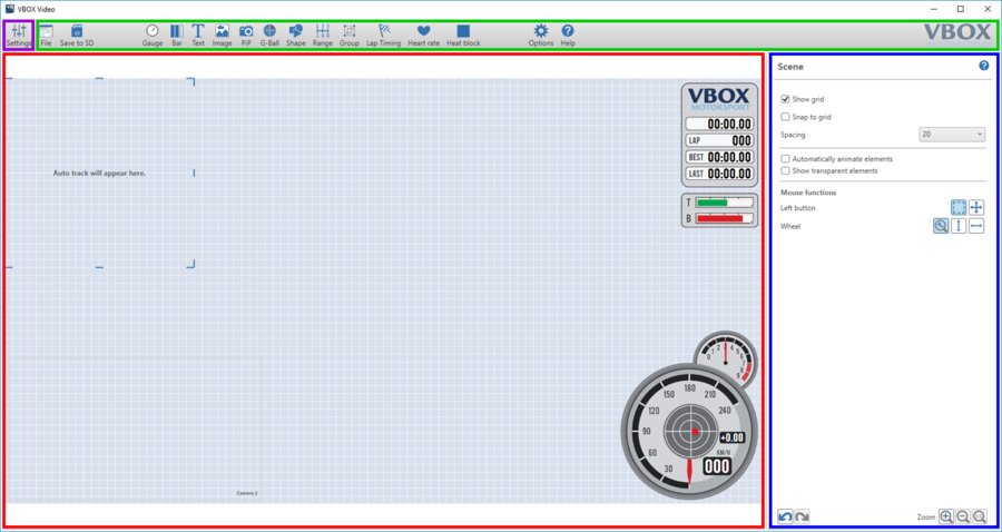
- The button highlighted in purple is the Main Settings button. This allows different screens to be accessed for CAN, Maths Channels, Performance Tests and General Settings.
- The green box highlights the Top Panel buttons which allow access to the supplied library of elements and scene files, as well as saving and uploading scene files.
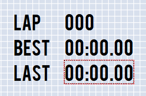
- The red box highlights the Main View area. This shows the current layout for all elements which will appear in the video overlay.
- The blue box highlights the Dynamic Settings panel. This will change depending on what is selected within the software, allowing different elements to be configured easily within one screen.
NOTE
Any changes made to the general scene settings within the 'dynamic settings panel' on the right will be saved by the software when it is closed.
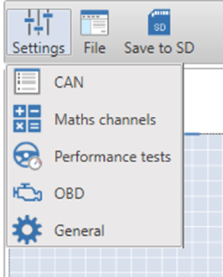
The settings button in the top left hand corner of the software allows the user to move between the main setup screens within VBOX Video Software. Clicking on any of the options here will clear the scene designer and populate the screen with settings options.
The settings button in the top left hand corner of the software allows the user to move between the main setup screens within VBOX Video Software. Clicking on any of the options here will clear the scene designer and populate the screen with settings options.

For more information on each of these settings windows, click on the relevant options below:
Clicking on the setting button will show the different settings windows. Select the settings option of interest.
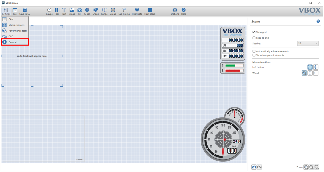
This will change the screen layout to display the selected settings options. To return to the scene designer, the settings button can be used again, or the quick access button, highlighted below.
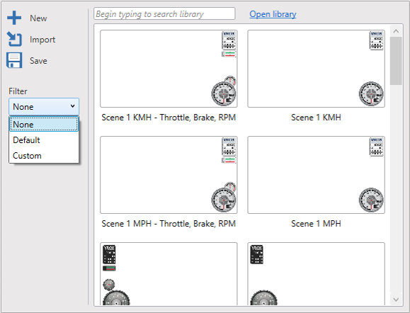
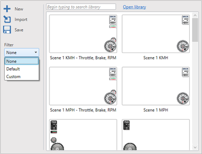
These buttons are used to save and load scene files, access the library of scenes and elements, as well as set up lap timing, access online help and set the software language.

This menu is focussed around saving and loading scene files.
Click here for more information on loading and saving scene files.
This menu is focussed around saving and loading scene files.
Click here for more information on loading and saving scene files.
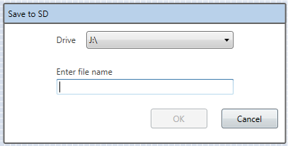
This allows you to save a scene file to an SD card or USB stick to allow it to be uploaded to the VBOX Video HD2. Ensure that scene file the on the root directory of an SD card (not in the media or any other folder).
This allows you to save a scene file to an SD card or USB stick to allow it to be uploaded to the VBOX Video HD2. Ensure that scene file the on the root directory of an SD card (not in the media or any other folder).
IMPORTANT
Scenes cannot be named 'default'.
NOTE
If a scene is saved and a file with the same name exists on the card/stick, the original will automatically have the file type suffix changed from '.vvhsn' to '.bak' and the new one will be saved as normal. To open the old one, manually change the file type suffix back to '.vvhsn' and it will work as normal.
Once a scene file has been saved to the SD card or USB stick using the 'Save to SD' button:
- Power up the VBOX Video HD2 unit with the cameras connected and without the SD card or USB stick inserted.
- Ensure the .vvhsn file(s) is located within the root directory of the SD card or USB stick (not in the media or any other folder).
- Load the SD card or USB stick into the front panel - the OK LED will flash green fast as the scene is loaded.
- The HD2 will double beep when the upgrade is complete - the OK LED will change to solid green.
- The new scene file will now be installed within your VBOX Video HD2 unit.
- To preview the new scene, the easiest method is to use the Camera Preview App.
NOTES
- It is possible to load up to 8 scene files to the unit for selection with an OLED Display. If more than 1 scene file is loaded and you don't have access to a display, the first scene alphabetically will be used by the unit. More information on this is available here.
- The scene file(s) will be removed from the memory storage when installed to the unit.
IMPORTANT
Scenes cannot be named as 'default'.
These buttons access the library of default and saved gauges allowing them to be easily added to any scene.
Click below for more information on each specific element:

If a PC has a Wi-Fi adapter installed, a Wi-Fi live camera preview is available within the Setup Software. This gives a video preview like within the Camera Preview App, and can be used to download a screenshot from the camera to use as a background.
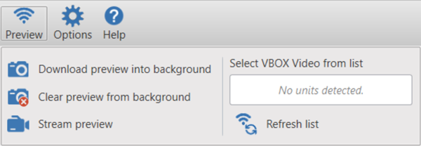
If a PC has a Wi-Fi adapter installed, a Wi-Fi live camera preview is available within the Setup Software. This gives a video preview like within the Camera Preview App, and can be used to download a screenshot from the camera to use as a background.

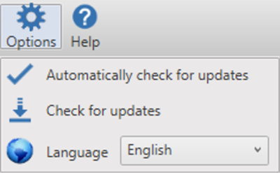
VBOX Video software will automatically check for any updates every time it is started up on a PC with an internet connection. This feature can be disabled here – we would recommend keeping this turned on.
If 'Automatically check for updates' has been disabled, you can manually check for updates by clicking on 'Check for updates'.
The software language to be displayed can also be changed here.
NOTE
The language cannot be changed once a Maths channel has been added.
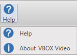
Access the main online help manual here.
Contextual help access is also available in different areas of the software – clicking on the ? icon anywhere in the software will take you to the help page for the currently selected item.
Access the main online help manual here.
Contextual help access is also available in different areas of the software – clicking on the ? icon anywhere in the software will take you to the help page for the currently selected item.

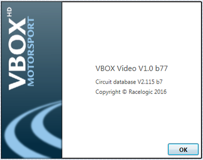
The about option listed within the help menu will display the current software version and circuit database version being used.

The about option listed within the help menu will display the current software version and circuit database version being used.
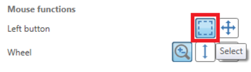
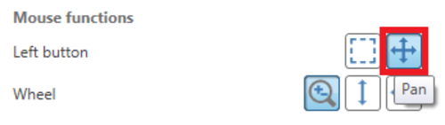
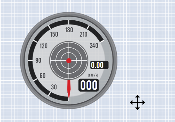
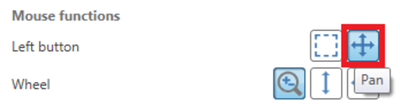
When no element is selected, the Dynamic Settings panel will show settings for mouse navigation. See the ‘Hotkeys’ table below for all mouse functions.
By default, the left mouse button is set to ‘select’ mode. This allows for easy selection of multiple elements when creating a temporary or fixed group.
Click and drag the left mouse button to select elements.

This allows the user to click and drag to pan around the scene.
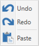
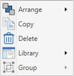
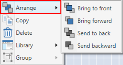
Right clicking within the scene will open an Options menu which will vary depending on whether you have clicked on an element or within an empty area. Available options include Arrange, Copy, Delete, Library, Group, Undo, Redo and Paste.


There are three options with regards to the mouse wheel function. The default setting is ‘zoom’ – this is highlighted in the image below.
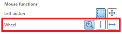

Allows the mouse wheel to zoom in/out on the main view window.

Allows the mouse wheel to zoom in/out on the main view window.

Allows the mouse wheel to move the main view window up and down when zoomed.

Allows the mouse wheel to move the main view window up and down when zoomed.

Allows the mouse wheel to move the main view window left and right when zoomed.

Allows the mouse wheel to move the main view window left and right when zoomed.
Additionally, clicking the mouse wheel at any time will return the screen to fully zoomed out.
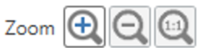
As well as the mouse wheel options shown above, there are manual zoom options available at all times in the bottom right hand corner of the software.
Here, the user is able to zoom in, zoom out, or return to full screen mode at any time.
As well as the mouse wheel options shown above, there are manual zoom options available at all times in the bottom right hand corner of the software.
Here, the user is able to zoom in, zoom out, or return to full screen mode at any time.

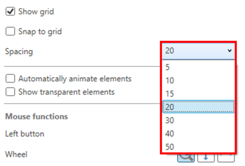
The background grid is useful when aligning elements. When no element is selected, the dynamic settings panel will show settings for the grid.
This setting can be turned on to aid with aligning text elements more easily. It is not recommended to leave this setting on all the time, as it will move elements slightly to snap to the grid every time they are re-located.
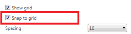


Grid spacing can be changed to suit the user’s preference or monitor.
Selecting this option will animate elements such as Gauge needles, G-Ball, Range, etc, so that you can see the expected output within the video.
This option shows/hides the border around elements that have been set as transparent, enabling you to see either the position of the elements within the scene or how the scene will be viewed within the video.
When elements are included within the scene, you can use the 'Bring to front' or 'Send to back' buttons to arrange the order in which they are viewed when overlapping each other.
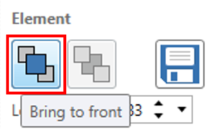
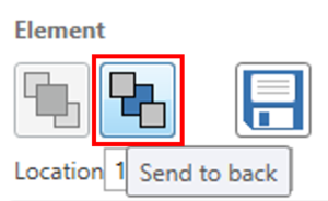


Elements can also be ordered by right clicking on the element(s) and selecting from the 'Arrange' menu.
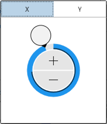
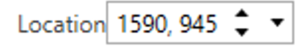
Along with being able to manually drag an element using the mouse, the location of an element can also be modified by either selecting the 'Location' text box and typing in a new location in the format x,y and pressing enter to accept the changes, by double clicking on either side of the comma to select either x or y component and manually entering text or using the up/down arrows, or by expanding the control to show a wheel that allows for faster positioning. This fine tuning is particularly useful when you are looking to align elements.
NOTE
If Snap to Grid is on and the user manually enters the new location, the location will snap to the nearest value below the entered value that aligns to the grid. For example, a grid spacing of 20 will snap to 0 for any value below 20, it will snap to 20 for any value greater than or equal to 20 but less than 40, etc.


The 'Undo' (Ctrl + Z) and 'Redo' (Ctrl + Y or Ctrl + shift + Z) buttons allow you to undo or redo any scene element changes you have made within the software.
Changes can also be undone/ redone by right clicking on an empty area within the scene and selecting either 'Undo' or 'Redo'.

The 'Undo' (Ctrl + Z) and 'Redo' (Ctrl + Y or Ctrl + shift + Z) buttons allow you to undo or redo any scene element changes you have made within the software.
Changes can also be undone/ redone by right clicking on an empty area within the scene and selecting either 'Undo' or 'Redo'.

NOTE
These options will not undo or redo any configuration settings changes made.
| Controls | Function |
|---|---|
| Left click | Select |
| Left click + drag | Multi-select / temporary group* |
| Left click + shift | Multi-select / temporary group |
| Right click | Right click menu access |
| Right click + drag | Pan |
| Mouse wheel | Zoom in/out* |
| Mouse wheel + shift | Scroll up/down |
| Mouse wheel + Ctrl | Scroll left/right |
| Ctrl + C | Copy selected element |
| Ctrl + V | Paste copied element |
| Ctrl + Y / Ctrl + shift + Z | Redo |
| Ctrl + Z | Undo |
| Delete key | Delete selected element |
*Configurable