
The Multi-Function Display (MFD) App allows VBOX Touch to operate as a display for a compatible VBOX unit (data logger or speed sensor). It presents live data from GPS-derived channels transmitted over CAN, delivering the same functionality as the standalone MFD Touch product.
It supports configurable display screens, parameter monitoring, and performance testing features.
The app can also calculate and display performance test results in real time, directly from the test vehicle.
Download the app from the VBOX Automotive website.
For installation instructions, refer to the Installing or Updating an App article.
1.5.5.119 – 12 September 2024
New Features
- Added ability to set alerts for the Trigger channel. The feature can now be used to notify the user when a digital light barrier has been crossed.
Bug Fixes
- Peak acceleration result now populate when using VB2SX.
1.5.5.113 – 1 August 2024
New Features
- Support for using display with VB2SX
- Support for using display with VBOX 4
Bug Fixes
- Distance parameter now resetting correctly from session data reset
1.5.3.103 – 3 August 2023
New Features
- Added Lap Timing testing; Able to perform circuit or point to point tests, with time at and ‘speed at’ results given for up to 6 separate split gates.
- Added VMAX Acceleration test type
- Added thermal printer compatibility; Test results will automatically print when an RLVBACS026 is connected.
- Added support for use with VBOX 3i ADAS
Improvements
- Kalman Filter status indicator updated to match VBOX 3i front panel behaviour.
- Increased IMU Kalman Filter status reports to improve user troubleshooting.
Bug Fixes
- Text colour no longer reset when changing selected parameter
- Acceleration and Deceleration tests no longer abort when IMU Kalman Filter is used and satellite reception is lost
- Removed stability issues caused by autosave file being blank.
1.4.1.65 – 12 August 2022
New Features
- Support added for new VBOX Touch hardware (V2).
1.4.1.64 – 27 July 2022
New Features
- Support added for product integration with with VB3iS range. Firmware Version 1.2.9388 or greater required.
- Support added for product integration with VBSS100 range. Firmware Version 1.8.1664 or greater required.
Improvements
- Distance parameter now continues to be calculated during GNSS dropouts with Kalman Filter utilised.
Bug Fixes
- Removed erroneous screen alerts when removing the penultimate screen.
- Small correction applied to 'Speed at Distance' result, when the test starts from stationary.
Version 1.3.1.68 - 07 March 2022
New features
- Ability to perform acceleration tests and to show the test parameters on screen.
- Ability to show VBOX internal CAN, external CAN, and AD channel information
- CF card icon and recording icon with the ability to control VBOX recording
- Additional indicators for statuses such as IMU Kalman filter and Dual Antenna
- Additional alerts and user feedback
- Test completion time and date added to results file
- Additional parameters added, such as current file name and media used
- Added centreline deviation test results for trigger and deceleration tests
Bug Fixes
- Improved time taken to add and remove additional screens
- Clearer borders for Analogue and G-Ball
- Various UI improvements, such as page numbers on the main screen
1.2.1.45 - 12 February 2021
New features
- Ability to add and remove screens (1-10 screen range)
- Analogue Gauge screen
- G-Ball screen
- Target Graph screen
- Horizontal Bar Graph screen
- Screenshot function
Improvements
- Parameter properties now reset after parameter channel/source is changed
Bug Fixes
- Improved dynamic resizing of text labels
- Various other UI improvements
- Re-applying current test configuration values no longer resets results
- Negative sign no longer counts towards character input limit
Version 1.1.1.26 - October 2020
- First commercial release
The table below shows which VBOX units are supported by the app, the app version where support was introduced, and any minimum firmware version required on the VBOX unit.
Where no minimum firmware version is listed, all firmware versions are supported unless stated otherwise.
If a VBOX unit requires a minimum firmware version, both conditions must be met:
- the app must be on the listed version or later
- the VBOX unit must be on the listed firmware version or later
| VBOX Unit | MFD App version | VBOX Unit Firmware Version |
|---|---|---|
| VBOX 4 | v1.5.5.113 and later | -- |
| VBOX 3i ADAS | v1.5.3.103 and later | -- |
| VBOX 3i | v1.1.1.26 and later | -- |
| VBOX 3iS | v1.4.1.64 and later | v1.2.9388 and later |
| VBOX IISX | v1.5.5.113 and later | -- |
| VBOX 100 Hz Speed Sensor | v1.4.1.64 and later | v1.8.1664 and later |
Connect VBOX Touch to a compatible VBOX unit using the appropriate CAN connection. Once connected, the app will display data received from the VBOX unit.
NOTE
Connecting VBOX Touch as MFD to a VBOX unit requires an RLCAB005-C cable.
Connect the RLCAB005-C cable between the Bottom CAN port on VBOX Touch and the RLCAN port on VBOX 4.
As Part of a Daisy Chain
If you want to use VBOX Touch as MFD as part of a daisy chain with a Racelogic module connected to VBOX 4, VBOX Touch must be connected at the end of the daisy chain.
Connect the RLCAB005-C cable between the Bottom CAN port on VBOX Touch and the RLCAN port on VBOX 3i ADAS.
Alternative Connection Options
Using VBOX CAN Hub
When using a VBOX CAN Hub with VBOX 3i ADAS, connect the RLCAB005-C cable between the Bottom CAN port on VBOX Touch and the MFD port on VBOX CAN Hub.
As Part of a Daisy Chain
If you want to use VBOX Touch as MFD as part of a daisy chain with a Racelogic module connected to VBOX 3i ADAS, VBOX Touch must be connected at the end of the daisy chain.
Connect the RLCAB005-C cable between the Bottom CAN port on VBOX Touch and the CAN port on VBOX 3i.
Alternative Connection Options
Using VBOX CAN Hub
When using a VBOX CAN Hub with VBOX 3i, connect the RLCAB005-C cable between the Bottom CAN port on VBOX Touch and the MFD port on VBOX CAN Hub.
As Part of a Daisy Chain
If you want to use VBOX Touch as MFD as part of a daisy chain with a Racelogic module connected to VBOX 3i, VBOX Touch must be connected at the end of the daisy chain.
Connect the RLCAB005-C cable between the Bottom CAN port on VBOX Touch and the CAN port on VBOX IISX.
Alternative Connection Options
Using VBOX CAN Hub
When using a VBOX CAN Hub with VBOX IISX, connect the RLCAB005-C cable between the Bottom CAN port on VBOX Touch and the MFD port on VBOX CAN Hub.
As Part of a Daisy Chain
If you want to use VBOX Touch as MFD as part of a daisy chain with a Racelogic module connected to VBOX IISX, VBOX Touch must be connected at the end of the daisy chain.
When the MFD App is installed on VBOX Touch, it requires the SD card to save and load settings, store test results, and update the firmware.
When an SD card is inserted in VBOX Touch, settings are retained after power cycles, and the last used screen is restored on startup.
If no SD card is inserted in VBOX Touch, settings are not saved, and will reset when the unit is powered off.
When using VBOX Touch as an MFD, the unit is powered via its connection to the VBOX unit.
On boot-up, the VBOX Touch will display a splash screen.
When VBOX Touch as an MFD is powered on for the first time, the 1 Parameter screen is displayed. On subsequent start-ups, provided an SD card is inserted, the last used screen will be restored.
The app displays live data from the connected VBOX unit across multiple screen layouts.
- 8 different screen types are displaying different combinations of parameters and gauges.
- A screen can display up to 6 defined VBOX parameters, depending on the selected layout.
- You can add up to 10 screens at a time.
Each screen includes a parameter display area, status indicators, and navigation controls.
The status indicators show information such as logging state, media status, and connection status, and the on-screen controls let you switch between display screens and navigate to the settings menus.
Navigate between screens and configure the display layouts directly within the app. You can add, remove and customise screens as required.
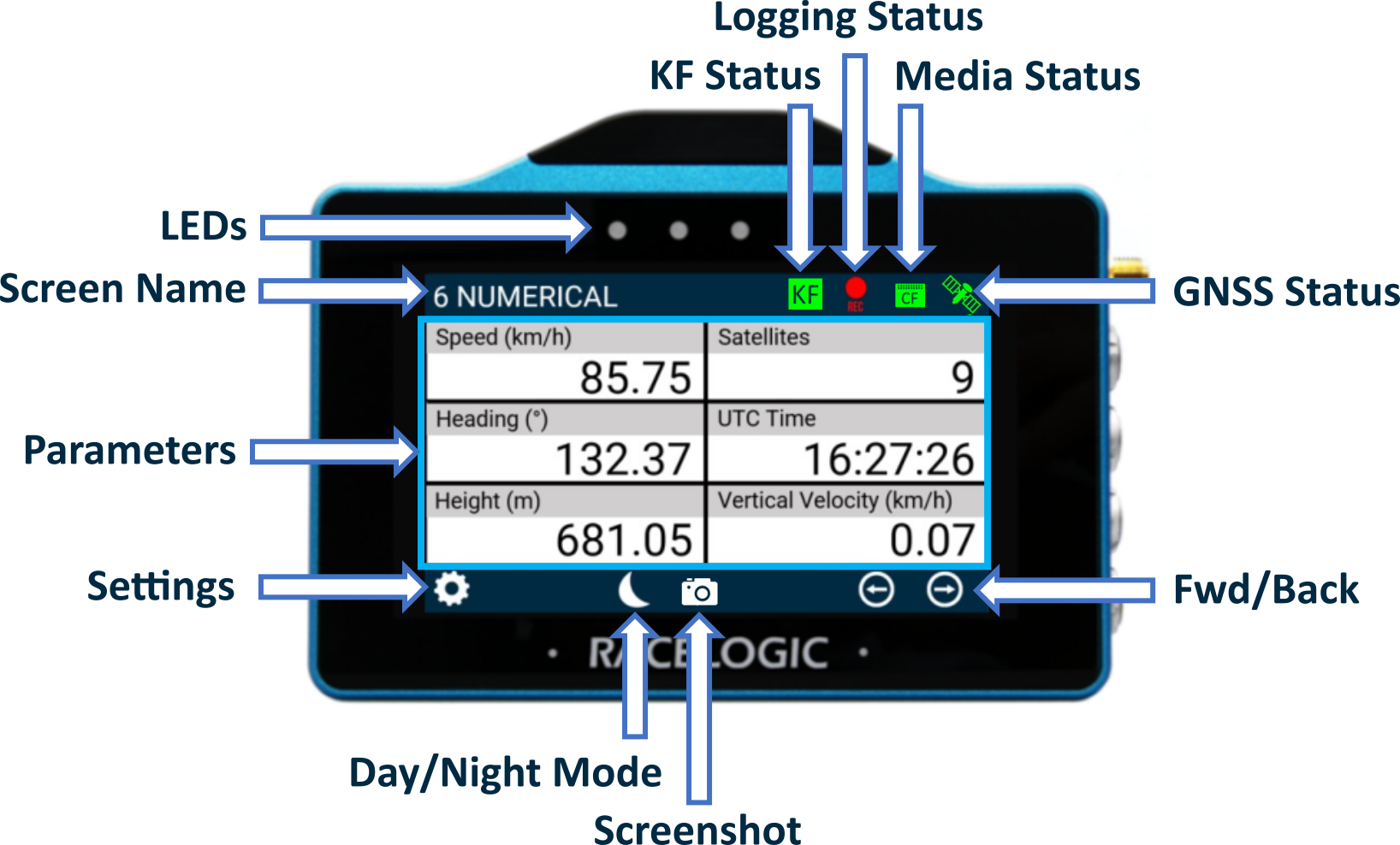
The Screen Name area in the screen header will display the name of the current data display screen.
You can change the name by either long-pressing or double-tapping the existing screen name.
The parameters displayed in the Parameters Area will depend on which screen you are currently on. Refer to the Numerical Settings section of this page for more information about how to configure them.
The table below contains an overview of the available parameters:
Standard parameters are sourced from the default Racelogic CAN output of the VBOX unit.
Deceleration test parameters are typically used for brake testing. Most of these require additional hardware, such as the VBOX Brake Trigger Switch or the VBOX Pedal Force Sensor with Event Marker Interface.
PRODUCT LIMITATION
In addition to the parameters in the table above, the following Standard Parameters are displayed when the VBOX Touch MFD App is used with VBOX 4 or VBOX 3i.
- Filename
- Logging Status
- Memory Used (%)
- KF Status

Tap the Settings button to open the Select Settings screen, where you can choose to open one of the following:
- VBOX Display Settings
- Decel Test Settings
- Accel Test Settings
- Lap Timing Settings
You can also save settings to or load settings from the SD card inserted in VBOX Touch.

Tap the Settings button to open the Select Settings screen, where you can choose to open one of the following:
- VBOX Display Settings
- Decel Test Settings
- Accel Test Settings
- Lap Timing Settings
You can also save settings to or load settings from the SD card inserted in VBOX Touch.


When available, use the Forward and Back buttons in the bottom right corner to navigate through the relevant screens.
Alternatively, you can swipe left or right on the screen.


When available, use the Forward and Back buttons in the bottom right corner to navigate through the relevant screens.
Alternatively, you can swipe left or right on the screen.

Enable Night Mode by tapping the Night Mode (moon symbol) button at the bottom of any screen.
The colour scheme will invert to suit night-time operation.
Tap the Night Mode button when in Night Mode to revert to Day Mode.

Enable Night Mode by tapping the Night Mode (moon symbol) button at the bottom of any screen.
The colour scheme will invert to suit night-time operation.
Tap the Night Mode button when in Night Mode to revert to Day Mode.
NOTE
Enabling Night Mode will reset any user-defined text colours.

Tap the Screenshot button to save an image of the current screen.
The image file will be saved to the SD card inserted in the display unit.
The LEDs will illuminate yellow in sequence from left to right to indicate the progress of writing to the SD card, and the display unit will emit an audible confirmation notification when the screen capture is complete.
If the display was unsuccessful in saving the screenshot (no SD card available or the card was full), it will display a 'NO SD CARD' message at the top of the screen, the LEDs will flash red twice, and it will emit an audible error notification.
Screenshots are saved as 1.5 MB bitmap images, oriented 90° from the original screen image, with the prefix 'screenshot'.
IMPORTANT
Do not remove the SD card while a screenshot is being captured. Doing so may cause the unit to crash.
PRODUCT LIMITATION
Only available when using with VBOX 4 and VBOX 3i.
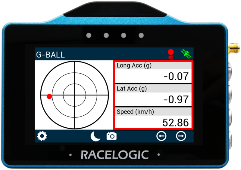
The Logging Status icon indicates the current logging status of the connected VBOX unit.
PRODUCT LIMITATION
Logging Status will not be displayed when connected to VBOX 3iS or VBOX Speed Sensor.

When the VBOX unit is logging data to the inserted media, the Logging Status icon will be red.

When the VBOX unit is logging data to the inserted media, the Logging Status icon will be red.

When the VBOX unit is not logging data to the inserted media, the Logging Status icon will be grey.

When the VBOX unit is not logging data to the inserted media, the Logging Status icon will be grey.
When a media card is detected and available in the VBOX unit (the Media Status icon is green), you can control the VBOX logging by pressing the Logging Status icon on the display.
If VBOX Touch cannot detect a connected VBOX unit, it will display a NO CAN message in place of the Logging Status icon.
A Logging Status channel is also available for selection as a text parameter which will describe the current logging status of the connected VBOX unit.
The GNSS Status (Satellite) icon displays the current GNSS status of the connected VBOX unit.
If MFD Touch cannot detect CAN transmission from a VBOX unit, you will see a 'NO CAN' message displayed in place of the indicator.

A green icon indicates Standalone positional accuracy/SBAS and Base Station DGPS corrections (Solution Types 1 or 2)

A green icon indicates Standalone positional accuracy/SBAS and Base Station DGPS corrections (Solution Types 1 or 2)

A purple icon indicates RTK Fixed (Solution Type 4).

A purple icon indicates RTK Fixed (Solution Type 4).

If there is a valid dual antenna lock, a superscript '2' will appear next to the relevant GNSS status icon.

If there is a valid dual antenna lock, a superscript '2' will appear next to the relevant GNSS status icon.

A flashing red icon indicates No satellite lock or IMU Coast (Solution Types 0 or 6)

A flashing red icon indicates No satellite lock or IMU Coast (Solution Types 0 or 6)

An orange icon indicates RTK Float (Solution Type 3)

An orange icon indicates RTK Float (Solution Type 3)

A white icon indicates Robot Position, local co-ordinates (Solution Type 5)

A white icon indicates Robot Position, local co-ordinates (Solution Type 5)
The LEDs at the top of the unit provide visual feedback for alerts, test events, and system actions.
Different colours indicate different types of events, such as speed alerts, parameter alerts, and test triggers.
The four LEDs at the top of the unit provide visual feedback for alerts and system actions.
LED Colours


Parameter Screens
LEDs Flash Blue
When a Target Speed LED Alert is set, the LEDs will flash blue when the target speed is reached.
LEDs Flash Blue
When a Target Speed LED Alert is set, the LEDs will flash blue when the target speed is reached.
LEDs Illuminate Red
When a Parameter LED Alert is set, the LEDs flash or remain solid red when the alert condition is met.
LEDs Illuminate Red
When a Parameter LED Alert is set, the LEDs flash or remain solid red when the alert condition is met.
LEDs Flash Green
- When Alert at Start is enabled, the LEDs flash green when the deceleration test start speed criteria are met.
- When Alert at Trigger is enabled, the LEDs flash green when the deceleration test is triggered.
- When Alert at End is enabled, the LEDs flash green when the deceleration test end condition is met.
LEDs Illuminate Yellow in Sequence
When a screenshot is being captured and saved, the LEDs will illuminate in yellow, in sequence from left to right, to display the progress of writing to the SD card.
Each LED will illuminate in yellow to represent 25% of the process being completed.
When all the LEDs have been illuminated and extinguished again, the file has been saved successfully.
Parameter Settings
LEDs Preview Alert Configuration Illuminated Red
When Parameter LED Alert is enabled, the LEDs display a red preview of the configured alert.
LEDs Preview Alert Configuration Illuminated Red
When Parameter LED Alert is enabled, the LEDs display a red preview of the configured alert.
General Settings
LEDs Flash Green
- When the unit is saving settings to an SD card
- When the unit is loading settings from an SD card
- When the unit is resetting session data
LEDs Flash Green
- When the unit is saving settings to an SD card
- When the unit is loading settings from an SD card
- When the unit is resetting session data
LEDs Flash Red
- When the unit is cancelling overwrite of an existing settings file
- When the unit is cancelling a reset
LEDs Flash Red
- When the unit is cancelling overwrite of an existing settings file
- When the unit is cancelling a reset
LEDs Flash Blue
When a Target Speed LED Alert is set
LEDs Flash Blue
When a Target Speed LED Alert is set
Test Settings
LEDs Flash Green
- When Alert at Start is enabled
- When Alert at Trigger is enabled
- When Alert at End is enabled
LEDs Flash Green
- When Alert at Start is enabled
- When Alert at Trigger is enabled
- When Alert at End is enabled
LEDs Flash Red
If Write Results File is enabled without an SD card inserted.
LEDs Flash Red
If Write Results File is enabled without an SD card inserted.
The MFD app can display up to 6 defined VBOX parameters. 8 different screen types are available, displaying a varying amount of parameters and gauges. You can add a maximum of 10 screens.
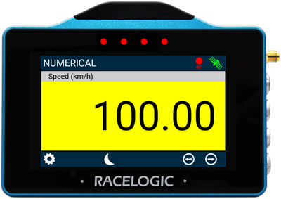
When the unit is booted up for the first time, the 1 Numerical screen will be presented by default.
If you want to add more screens, tap the Forward arrow at the bottom right of the screen or swipe left to access the Add/Remove screen.
The Add/Remove screen will always be located after the last Data Display screen.
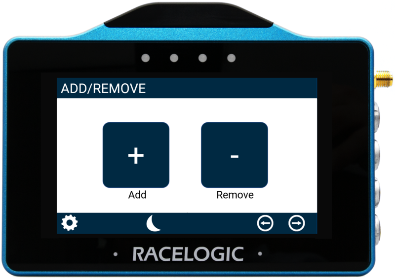
Tap the Add button to add a new screen.
This will open up the Add Page selection screen where you can choose which display you would like. Swipe the screen left or right, or use the Next or Previous arrows on the sides of the screen to navigate through the available screens:
- 1 NUMERICAL
- 3 NUMERICAL
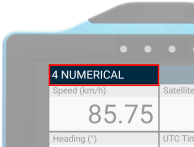
- 4 NUMERICAL
- 6 NUMERICAL
- ANALOGUE GAUGE
- G-BALL
- TARGET
- BAR GRAPH
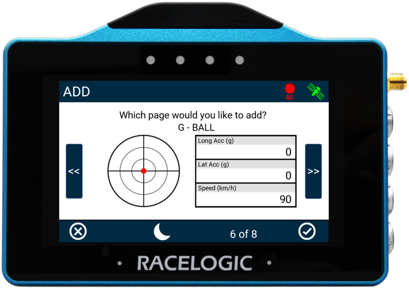
Tap the Confirm button in the bottom right corner to add the selected screen. Tap the Cancel button in the bottom left corner to return the Add/Remove screen without saving.
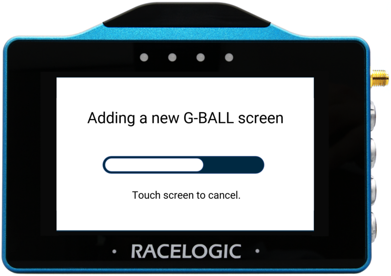
If confirmed, a progress screen will be displayed along with a countdown.
If you would like to cancel the addition of the screen, tap on the screen before the countdown runs out.
Remove a screen by tapping the Remove button in the Add/Remove screen, selecting the screen you want to remove, and tapping the Confirm button.
Change the name of each parameter screen by either long-pressing or double-tapping the existing screen name in the top bar of the display.
Use the presented keypad to enter the new screen name.
Save the new name by tapping the Confirm button in the bottom right corner.
When VBOX Touch has an inserted an SD card, the unit will remember the value after each power cycle.
Tap the Cancel button in the bottom left corner to return to the data display screen without saving.


Configure a parameter on a data display screen by long-pressing or double-tapping the existing parameter to open display-specific settings.
When you have finished adding screens, you can move between the screens with the Forward or Back arrows in the bottom right corner or by swiping left or right on the screen.
Find more information about the different data displays and their respective settings by clicking on a display type below:
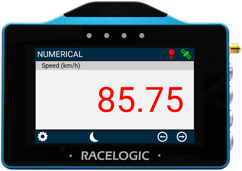
There are 4 screens available. You can display either 1, 3, 4 or 6 parameters. The first time that the unit is booted up with the MFD App, the 1 Parameter screen will be presented by default. The applies units depend on what is selected in the VBOX Display Settings.
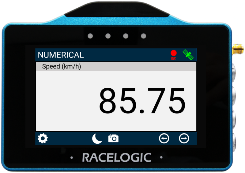
1 Numerical Screen
Default Parameter:
- Speed
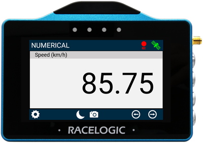
1 Numerical Screen
Default Parameter:
- Speed
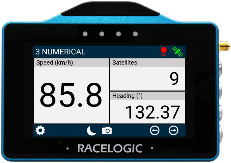
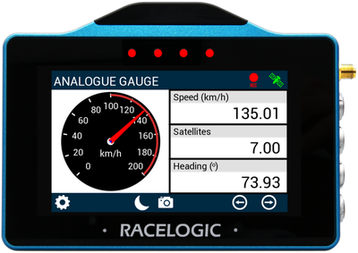
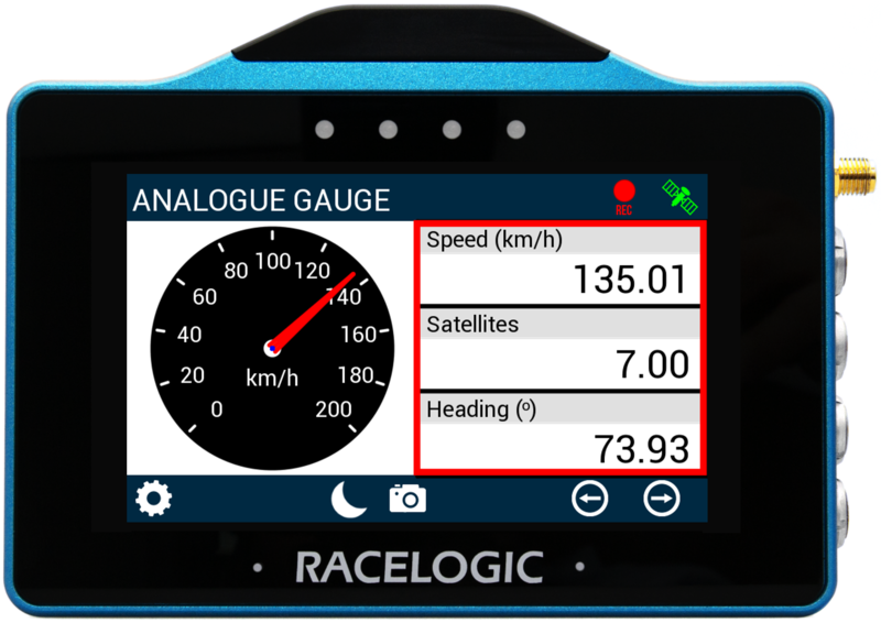
3 Numerical Screen
Default parameters:
- Speed
- Satellites
- Heading
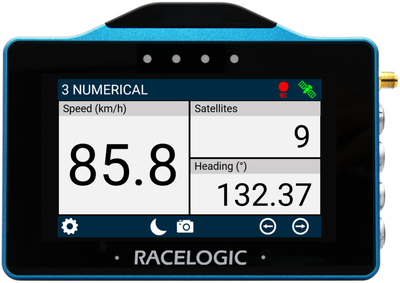
3 Numerical Screen
Default parameters:
- Speed
- Satellites
- Heading
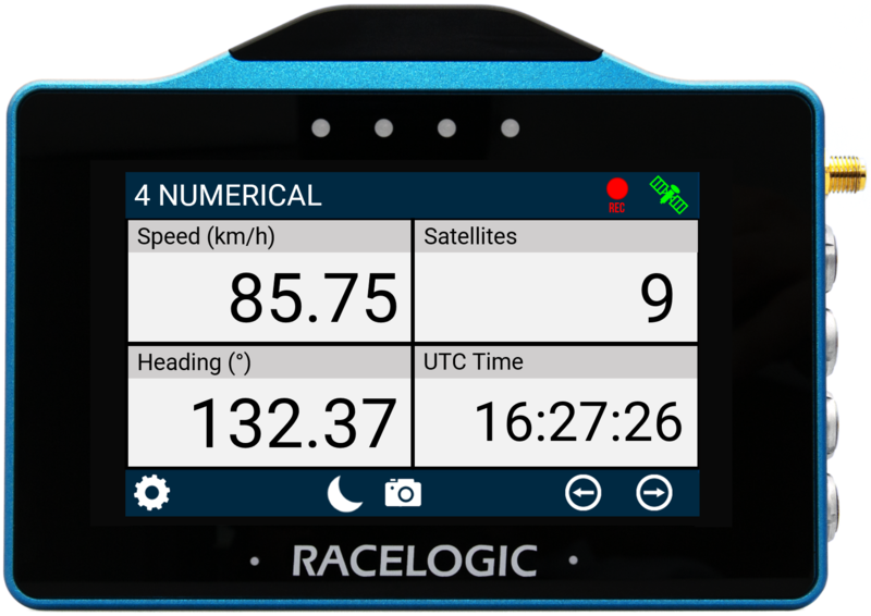
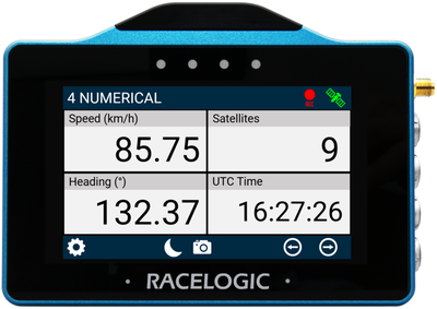
4 Numerical screen
Default parameters:
- Speed
- Satellites
- Heading
- UTC Time
4 Numerical screen
Default parameters:
- Speed
- Satellites
- Heading
- UTC Time
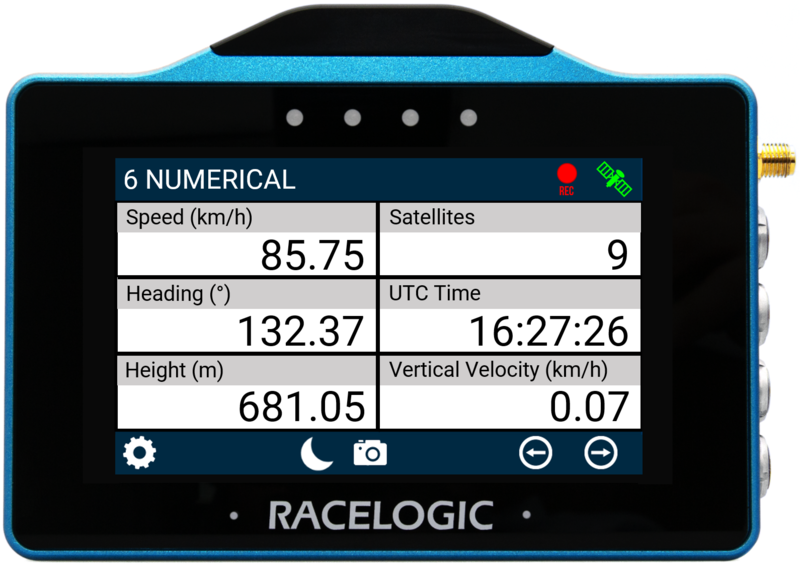
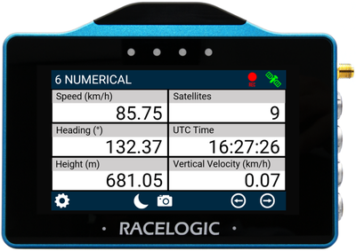
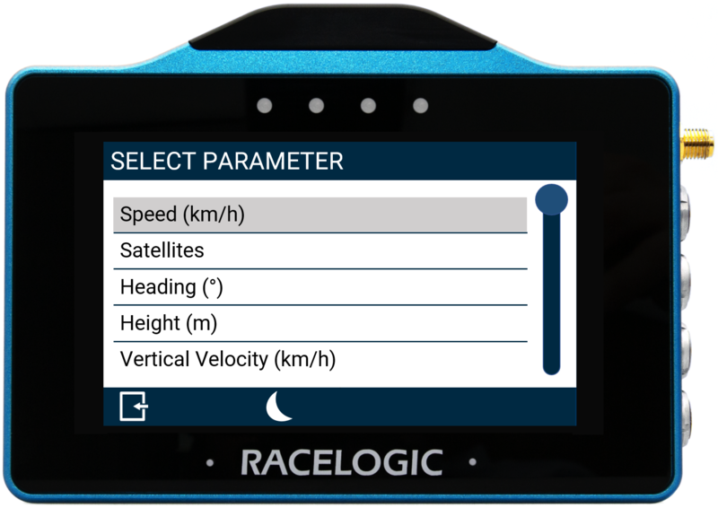
6 Numerical Screen
Default parameters:
- Speed
- Satellites
- Heading
- UTC Time
- Height
- Vertical Velocity
6 Numerical Screen
Default parameters:
- Speed
- Satellites
- Heading
- UTC Time
- Height
- Vertical Velocity
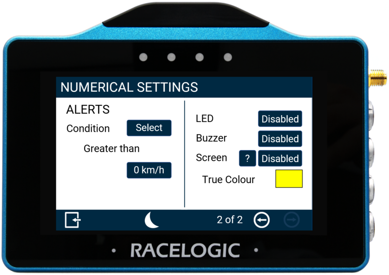
Numerical Settings
You can configure each parameter on a numerical screen by either long-pressing or double-tapping the existing parameter in the parameter area.
This will open the Numerical Settings menus.
There are 2 numerical settings screens available, the Data settings screen and the Alerts settings screen.
Move between the screens with the Forward or Back arrows in the bottom right corner or by swiping left or right on the screen.
Change settings by tapping the value button for each option.
Tap the Exit button in the bottom left corner to return to the Numerical Data Display screen.
NOTE
If you have an SD card inserted in VBOX Touch, the setting values will be remembered after each power cycle.
Numerical Settings - Data
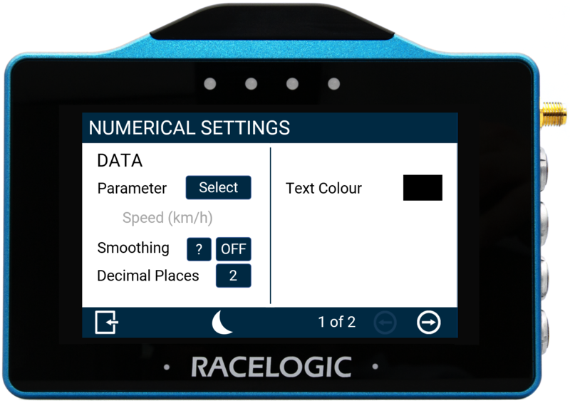
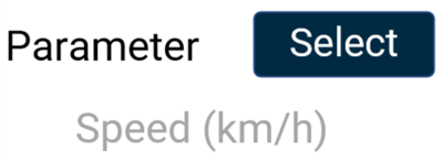
Parameter
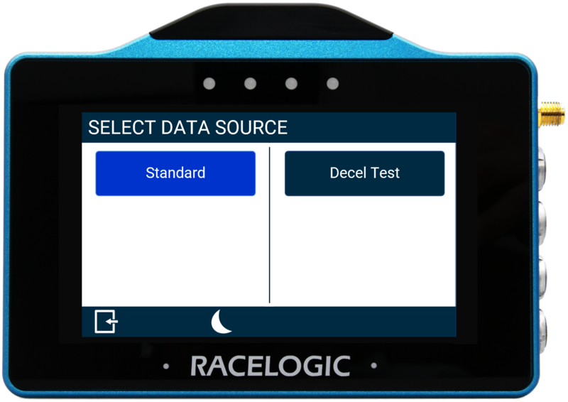
Change a parameter by tapping the Select button to open the Data Source menu where you can choose from Standard and Decel Test parameters.
You can assign any data parameter that is available from the connected VBOX unit along with any calculated test results from the MFD app to the selected numerical element.

NOTE
The currently selected parameter is displayed in grey beneath the option.
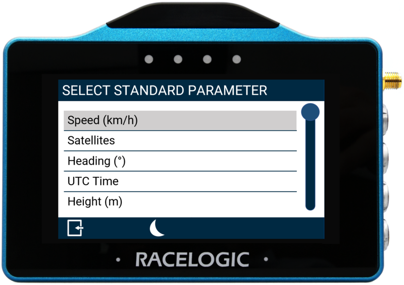

Use the scroll bar on the right-hand side of the selection screen to go through the options and tap the desired parameter to select it.
Return to the settings screen without saving by selecting the Exit button in the bottom left corner.
Smoothing
Apply smoothing to the live speed values on the display if required.
The input value determines the number of previous data samples used to smooth the displayed data. It does not affect any of the performance results or the logged data of the connected unit.
Enable smoothing by tapping on the current value (off by default) and use the presented keypad to enter the number of previous data samples you would like to use for the smoothing.

Save the selected value by tapping the Confirm button in the bottom right corner.
Tap the Cancel button in the bottom left corner to return to the Settings screen without saving.
NOTES
- The maximum input value is 99.
- Smoothing can introduce a slight delay to the displayed value.
- The setting will be greyed out and disabled if the numerical parameter being configured is UTC Time, Longitude, or Latitude.
Decimal Places
Select how many decimal places are used to represent the nominated data for the selected numerical element.
Available options are 0, 1, 2 and 3. The default setting is 2.
The exception is integer-only channels, including Satellites, Trigger Test Number, Decel Test Number, and UTC Time, which do not have any decimal points.

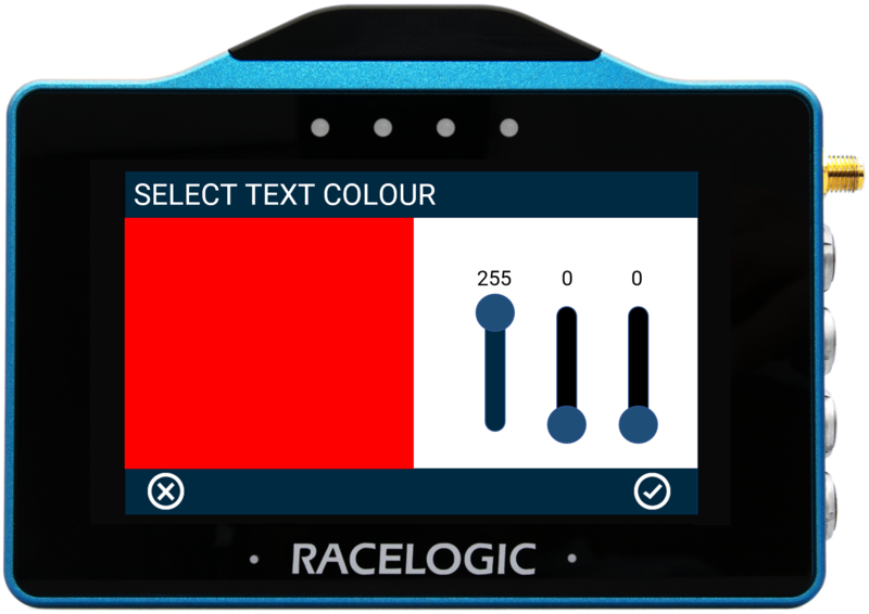
Text Colour
Define the text colour of the numerical element data.
Tap the current colour (black by default) to open the Select Text Colour screen.
Use the RGB sliders to define the new colour. The area to the left of the sliders provides a colour preview.
Save the selected colour by tapping the Confirm button in the bottom right corner.
Tap the Cancel button in the bottom left corner to return the Numerical Settings screen without saving.

NOTES
- Changing the text colour applies to the data text only, it does not apply to the parameter label.
- If you enable Night Mode, all user-defined text colours will be reset.
Numerical Settings - Alerts
NOTE
The Alert settings will be greyed out and disabled if the numerical parameter that is being configured is UTC Time, Longitude, or Latitude.
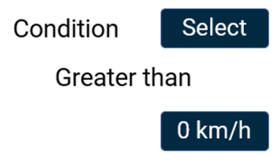
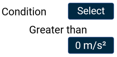
Condition
This option allows you to define an alert condition.
Tap the Select button to cycle through the available conditions:
- Equal To
- Not Equal To
- Less Than
- Less Than or Equal To
- Greater Than (default)
- Greater Than or Equal To
- Between
- Not Between
Define the alert condition value(s) by tapping the value box and using the presented keypad to enter the required value(s).

Save the selected value by tapping the Confirm button in the bottom right corner.
Tap the Cancel button in the bottom left corner to return to the Numerical Settings screen without saving.
LED
Select this option to enable a solid or flashing visual alert when the Defined Alert Condition is met. Press the button to cycle through the options, the device will preview the setting with the 4 red LEDs across the top of the unit.

Select this option to enable a solid or flashing visual alert when the Defined Alert Condition is met. Press the button to cycle through the options, the device will preview the setting with the 4 red LEDs across the top of the unit.

Buzzer
Select this option to enable a sound alert (beep) when the Defined Alert Condition is met.

Select this option to enable a sound alert (beep) when the Defined Alert Condition is met.

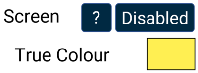
Screen
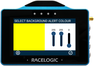
Enable a screen alert for when the Defined Alert Condition is met.
Once the alert condition is met, the background of the parameter will change colour.
Tap the current colour (yellow by default) and use the presented RGB sliders to define the required colour. The area to the left of the sliders will provide a colour preview.
Save the selected colour by tapping the Confirm button in the bottom right corner.
Tap the Cancel button in the bottom left corner to return the Numerical Settings screen without saving.


NOTE
If you enable Night Mode, this will reset the user-defined alert colour.
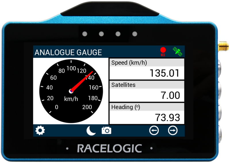
The Analogue Gauge screen contains an analogue needle gauge with 3 supporting numerical elements. The applied units depend on what is selected within the VBOX Display Settings.
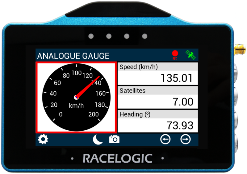
Analogue Gauge Element
The analogue needle gauge element is located on the left hand side of the screen, it provides a visual representation of a selected parameter (speed by default).
The gauge can be configured by either long-pressing or double-tapping on it. This will open up the Analogue Gauge Settings screens.
There are 2 Analogue Gauge settings screens available, the Data/Range screen and the Alerts screen.
Use the Forward and Back arrows in the bottom right corner of the screen to move between the settings screens, or swipe left or right on the screen.
Change settings by tapping on the corresponding button next to an option.
Return to the parameter screen by tapping the Exit button in the bottom left corner.
NOTE
When an SD card is inserted, settings values will be remembered after each power cycle.
Analogue Gauge Settings - Data/Range
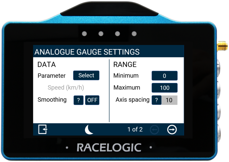
Data Settings
Parameter
The gauge parameter is set as Speed by default, but can be changed by tapping the Select button to open the parameter list. You can assign any data parameter that is available from the connected VBOX to the Analogue Gauge (apart from UTC Time, Longitude or Latitude).
The gauge parameter is set as Speed by default, but can be changed by tapping the Select button to open the parameter list. You can assign any data parameter that is available from the connected VBOX to the Analogue Gauge (apart from UTC Time, Longitude or Latitude).
NOTE
The currently selected parameter is displayed in grey beneath the option.
Use the scroll bar on the right-hand side of the selection screen to navigate through the options and tap the desired parameter to confirm.
Return to the settings screen without saving by tapping the Exit button on the bottom left.
Smoothing
If required, you can smooth the Analogue Gauge data.
The input value determines the number of previous data samples used to smooth the displayed data. It does not affect any of the performance results or the logged data from the connected unit.
You can enable smoothing by tapping the current value (off by default) and using the keypad presented to enter the number of previous data samples you would like to use in the display smoothing.
Save the selected value by tapping the Confirm button in the bottom right-hand corner.
Tap the Cancel button in the bottom left-hand corner to return to the Settings Screen without saving.
NOTES
- The maximum input value is 99.
- Smoothing can introduce a slight delay to the displayed value.
Range Settings
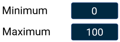
Minimum/Maximum
Define the minimum and maximum range values for the Analogue Gauge element's axes.
Tap the value boxes and use the presented keypads to enter the required values (set as 0 and 100 by default).
Save the chosen values by tapping the Confirm button in the bottom right-hand corner.
Tap the Cancel button in the bottom left-hand corner to return to the Settings Screen without saving.

NOTES
- The maximum input value is 99999.
- The minimum input value is -99999 (when the signed parameter is selected, otherwise 0).
- One decimal place resolution available.
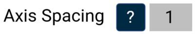
Axis Spacing
The Axis spacing value tells you how much spacing there is between each gauge increment marker. The value will change depending on the Minimum/Maximum range values.
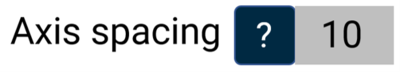
The Axis spacing value tells you how much spacing there is between each gauge increment marker. The value will change depending on the Minimum/Maximum range values.

Analogue Gauge Settings - Alerts
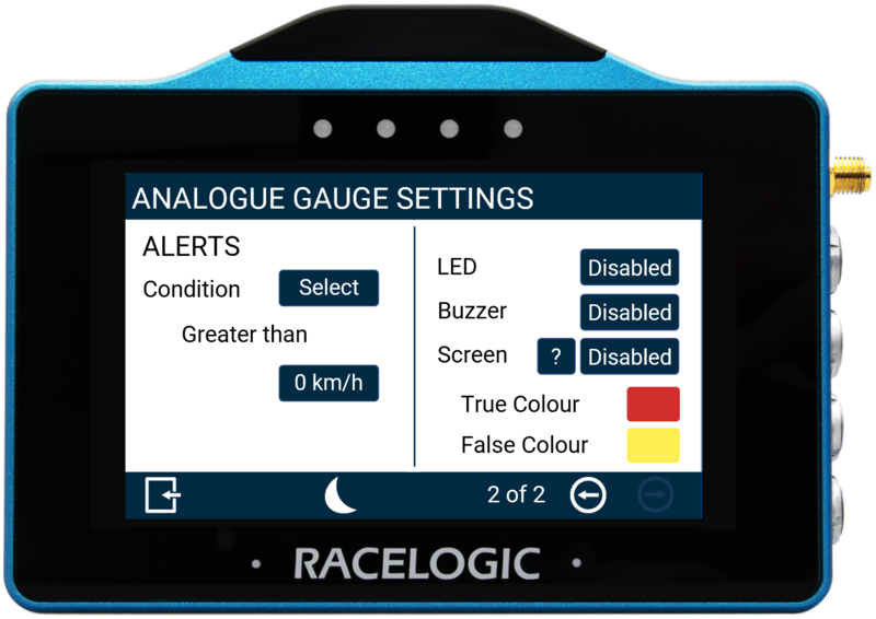
Condition
This option allows you to define an alert condition.
Tap the Select button to cycle through the available conditions:
- Equal To
- Not Equal To
- Less Than
- Less Than or Equal To
- Greater Than (default)
- Greater Than or Equal To
- Between
- Not Between
Define the alert condition value(s) by tapping the value box and using the presented keypad to enter the required value(s).
Save the selected condition by tapping the Confirm button in the bottom right-hand corner.
Tap the Cancel button in the bottom left-hand corner to return to the Settings Screen without saving.
LED
Select to enable a solid or flashing visual alert when the Defined Alert Condition is met.
Tap the button to cycle through the options, the device will preview the setting with the 4 red LEDs across the top of the unit.
Select to enable a solid or flashing visual alert when the Defined Alert Condition is met.
Tap the button to cycle through the options, the device will preview the setting with the 4 red LEDs across the top of the unit.
Buzzer
Enable a sound alert (beep) when the Defined Alert Condition is met.
Enable a sound alert (beep) when the Defined Alert Condition is met.
Screen
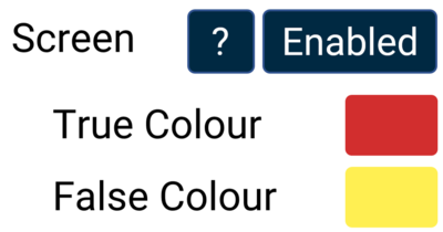
Enable a screen target zone in relation to the Defined Alert Condition.
If the value has yet to be achieved, the 'False Colour' will appear within the target zone, once the value is achieved, the 'True Colour' will appear within the target zone.
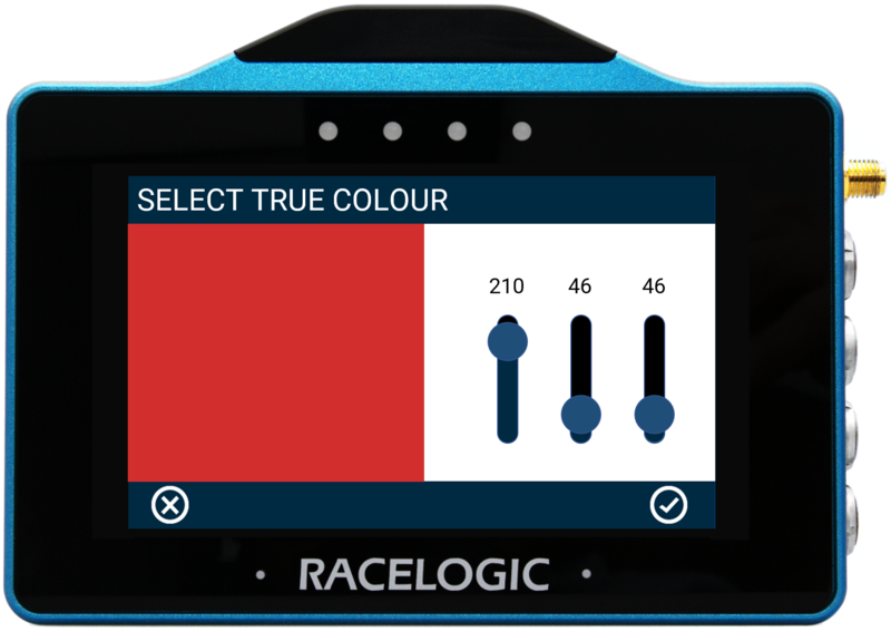
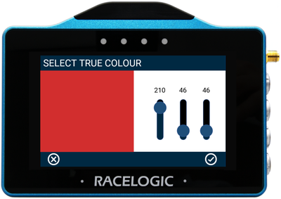
To change the True and False target zone alert colours, tap the current colours (yellow and red by default) to Select Colour screens.
Use the presented RGB sliders to define the required colours. The area to the left of the sliders provides a colour preview.
To save a colour, tap the Confirm button in the bottom right corner.
Tap the Cancel button in the bottom left corner to return to the Settings Screen without saving.

Enable a screen target zone in relation to the Defined Alert Condition.
If the value has yet to be achieved, the 'False Colour' will appear within the target zone, once the value is achieved, the 'True Colour' will appear within the target zone.
To change the True and False target zone alert colours, tap the current colours (yellow and red by default) to Select Colour screens.
Use the presented RGB sliders to define the required colours. The area to the left of the sliders provides a colour preview.
To save a colour, tap the Confirm button in the bottom right corner.
Tap the Cancel button in the bottom left corner to return to the Settings Screen without saving.

Numerical Elements
The 3 numerical elements are located on the right-hand side of the screen and include Speed, Satellites and Heading parameters by default.
Each parameter can be configured separately.
Long-press or double-tap the existing parameter area. This will open the Numerical Settings for the parameter.
Refer to the Numerical Settings section under Numerical Screens above for more information about the available settings.
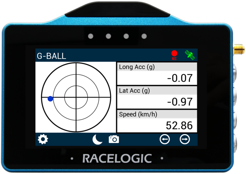
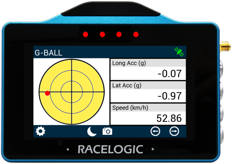
The G-Ball screen contains a G-Ball gauge with 3 supporting numerical elements. The applied units depend on what is selected in the VBOX Display Settings.
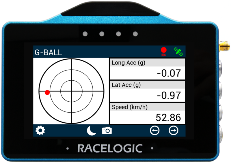
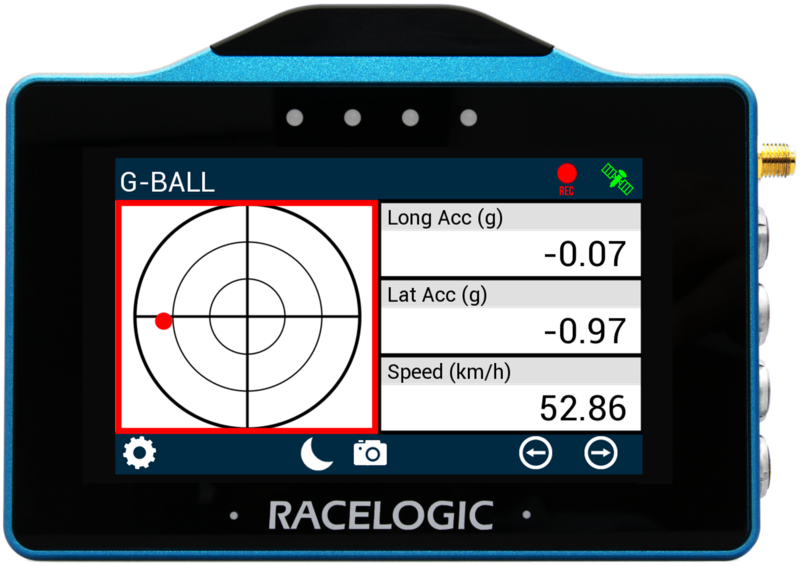
G-Ball Element
The G-Ball element is located on the left hand side of the screen, it provides a visual representation of the longitudinal and lateral acceleration parameters.
Configure the gauge by either long-pressing or double-tapping on it to open the G-Ball Settings.
There are 2 G-Ball settings screens available, the Data/Range screen and the Alerts screen.
Use the Forward or Back arrows in the bottom right of the screen to navigate between the settings screens or swipe left or right on the screen.
Change settings by tapping on the corresponding button next to an option.
Return to the parameter screen by tapping the Exit button in the bottom left corner.
NOTE
When an SD card is inserted, settings values will be remembered after each power cycle.
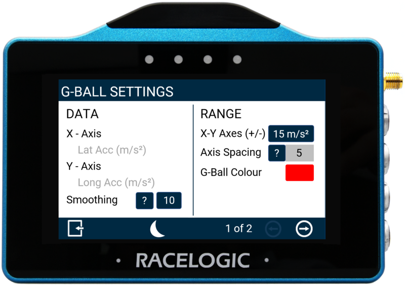
G-Ball Settings - Data/Range
Data Settings
X-Axis / Y-Axis
This area displays which acceleration parameters are associated with which G-Ball gauge axis (X-axis: lateral acceleration, Y-axis: longitudinal acceleration).
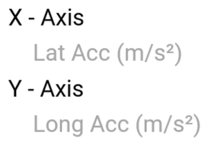
This area displays which acceleration parameters are associated with which G-Ball gauge axis (X-axis: lateral acceleration, Y-axis: longitudinal acceleration).

Smoothing
Apply smoothing to the G-Ball gauge data if required.
The input value determines the number of previous data samples used to smooth the displayed gauge data. It does not affect any of the performance results or the logged data of the connected unit.
The SMOOTHING VALUE is set to 10 samples by default. You can change this value or turn off the smoothing by pressing the current value and using the presented keypad to enter the number of previous data samples you would like to use in the display smoothing.
Save the selected value by tapping the Confirm button in the bottom right-hand corner.
Tap the Cancel button in the bottom left-hand corner to return to the Settings Screen without saving.

NOTES
- The maximum input value is 99.
- Smoothing can introduce a slight delay to the displayed value.
Range Settings
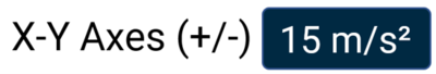
X-Y Axes (+/-)
This option allows you to define an absolute range for the G-Ball element's axes. Press on the value box and use the presented keypad to define the required value.
Save the chosen value by pressing the Confirm button in the bottom right corner. Press the Cancel button in the bottom left corner of the screen to return to the Settings screen without saving.
NOTES
- The maximum input value is 999.
- The minimum input value is 0.1.
- One decimal place resolution is available to values under 100.
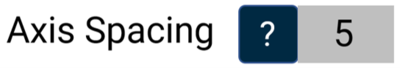
Axis Spacing
The Axis Spacing value tells you how much spacing there is between each gauge increment marker. The value changes depending on the X-Y Axes Range Value.

The Axis Spacing value tells you how much spacing there is between each gauge increment marker. The value changes depending on the X-Y Axes Range Value.
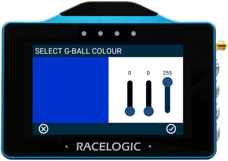
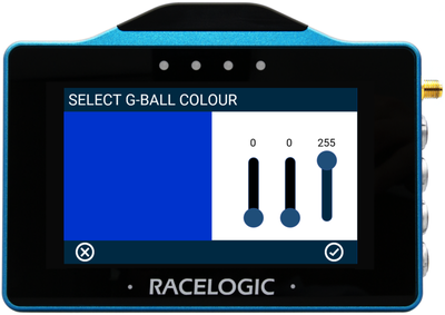
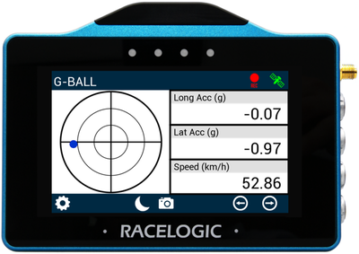
G-Ball Colour
Change the colour of the G-Ball in the gauge element by tapping the current colour (red by default) to open the colour selection screen. Use the presented RGB sliders to define your new colour. The area to the left of the sliders provides a colour preview.
Save the new colour by tapping the Confirm button in the bottom right corner.
Tap the Cancel button in the bottom left corner to return to the Settings Screen without saving.

G-Ball Settings - Alerts
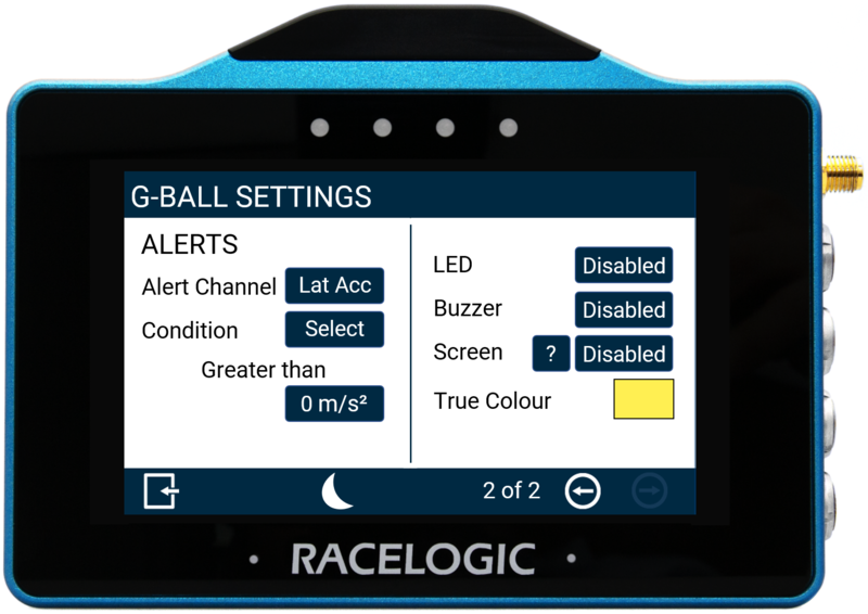
Alert Channel
This option allows you to define an alert channel. Tap the Select button to toggle between lateral and longitudinal acceleration.

This option allows you to define an alert channel. Tap the Select button to toggle between lateral and longitudinal acceleration.

Condition
Change the alert condition by tapping the Select button to cycle through the available conditions:
- Equal To
- Not Equal To
- Less Than
- Less Than or Equal To
- Greater Than (default)
- Greater Than or Equal To
- Between
- Not Between
Set the alert condition value(s) by tapping the value box and using the presented keypad to enter the required value(s).
Save the selected value by tapping the Confirm button in the bottom right corner.
Tap the Cancel button in the bottom left corner to return to the Settings Screen without saving.
LED
Select this setting to enable a solid or flashing visual alert when the Defined Alert Condition is met. Tap the button to cycle through the options. The device will preview the setting with the 4 red LEDs across the top of the unit.
Select this setting to enable a solid or flashing visual alert when the Defined Alert Condition is met. Tap the button to cycle through the options. The device will preview the setting with the 4 red LEDs across the top of the unit.
Buzzer
Select to enable an audible alert when the defined Alert Condition is met. The MFD Touch will beep when this setting is enabled.
Select to enable an audible alert when the defined Alert Condition is met. The MFD Touch will beep when this setting is enabled.
Screen
Enable a screen alert when the Defined Alert Condition is met.
Once the value is achieved, the background of the parameter will change colour.
Tap the current colour (yellow by default) to open the colour selection screen. Use the presented RGB sliders to define your new colour. The area to the left of the sliders provides a colour preview.
Save your colour selection by tapping the Confirm button in the bottom right corner.
Tap the Cancel button in the bottom left corner to return to the Settings Screen without saving.
Numerical Elements
The 3 numerical elements are located on the right hand side of the screen and include Longitudinal Acceleration, Lateral Acceleration and Speed parameters by default.
Configure a parameter by either long-pressing or double-tapping the existing parameter area. This will open up the Numerical Settings menus.
Refer to the Numerical Settings in the Numerical Screens section above for more information about the available settings.
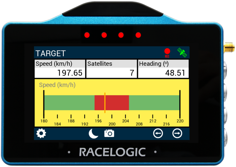
The Target screen contains a target gauge with 3 supporting numerical elements. The applied units depend on what is selected in the VBOX Display Settings.
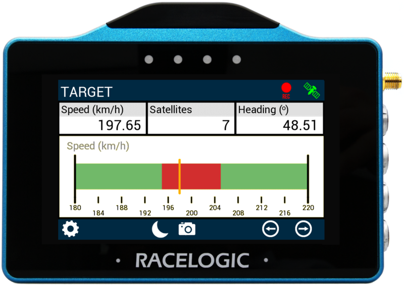
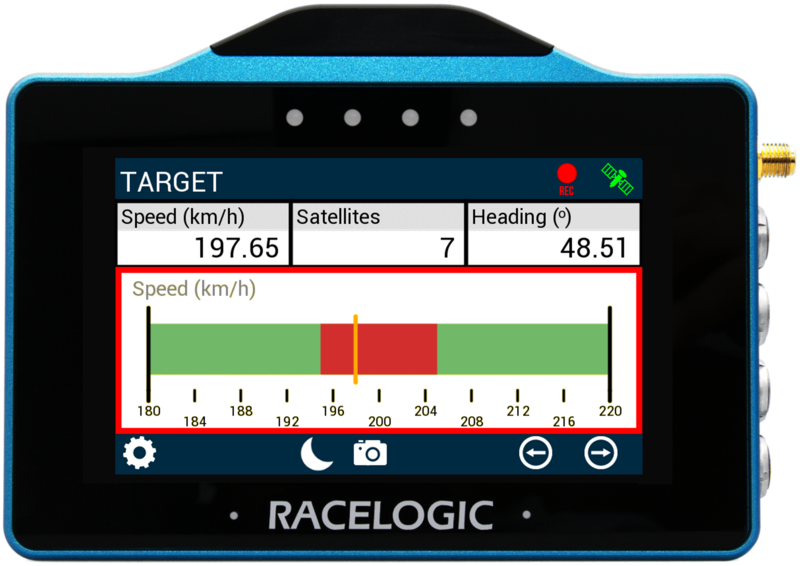
Target Element
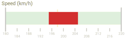
The Target Graph gauge element is located on the bottom of the screen, it provides a visual representation of a selected parameter (speed by default).
Configure the gauge by either long-pressing or double-tapping on it and open the Target Graph Settings.
There are 2 Target Graph settings screens available, the Data/Range settings and the Colours/Alert settings.
Use the Forward or Back arrows in the bottom right corner to move between the screens or swipe left or right on the screen.
Change a settings by tapping on the corresponding button next to an option.
Return to the parameter screen, by tapping the Exit button in the bottom left corner.
NOTE
If an SD card is inserted, settings values will be remembered after each power cycle.
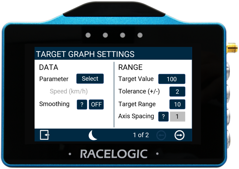
Target Graph Settings - Data/Range
Data Settings
Parameter
The gauge parameter is set as Speed by default, but you can change it by tapping the Select button to open the parameter list.
You can assign any available data parameter from the connected VBOX to the Target Gauge (apart from UTC Time, Longitude or Latitude).
The gauge parameter is set as Speed by default, but you can change it by tapping the Select button to open the parameter list.
You can assign any available data parameter from the connected VBOX to the Target Gauge (apart from UTC Time, Longitude or Latitude).
NOTE
The currently selected parameter is displayed in grey beneath the option.
Use the scroll bar on the right hand side of the selection screen to scroll through the options and tap the required parameter to select it.
Return to the settings screen without saving, by tapping the Exit button in the bottom left corner.
NOTE
If a previously selected CAN channel parameter is no longer available, the values for that parameter will display as zero or nil. The parameter reference name will be greyed out and 'MISSING PARAMETER' will flash in the header of the screen.
Smoothing
You can smooth the Target data if required. The input value determines the number of previous data samples used to smooth the displayed data. It does not affect any of the performance results or the logged data of the connected unit.
To enable smoothing, press the current value (off by default) and use the presented keypad to enter the number of previous data samples you would like to use within the display smoothing.
Save your selected value by tapping the Confirm button in the bottom right corner.
Tap the Cancel button in the bottom left corner to return to the Settings Screen without saving.
NOTES
- The maximum input value is 99.
- Smoothing can introduce a slight delay to the displayed value.
Range Settings
Target Value
The target value will be located at the centre of the gauge. You can define this by pressing the value box and using the presented keypad to define the required value (set as 240 by default).
Save your selected value by tapping the Confirm button in the bottom right corner.
Tap the Cancel button in the bottom left corner to return to the Settings Screen without saving.

NOTES
- The maximum input value is 99999.
- The minimum input value is -99999 (when the signed parameter is selected, otherwise 0).
- One decimal place resolution is available to values under 10000.
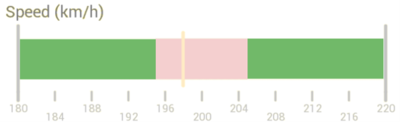
Tolerance (+/-)
Define the tolerance (target zone) displayed on either side of the target value. You can define the colour used for this zone (red by default) in the Colours Settings.
The value is set to 2 by default. Tap the value button and use the presented keypad to enter a new value.
When using the default +/- tolerance value of 2 for a target value of 100, the target zone would be between 98 and 102.
Save the new value by tapping the Confirm button in the bottom right corner.
Tap the Cancel button in the bottom left corner to return to the Settings Screen without saving.

NOTES
- The maximum input value is 9999.
- The minimum input value is 0.1.
- One decimal place resolution is available to values under 1000.
Target Range
Change the range of the background bar.
Change the colour used for the bar (green by default) by tapping on the Bar option in the Colours Settings.
Tap the value box and use the presented keypad to enter the required value, (10 by default).
Example: Wen using the default range value of 10 for a target value of 100, the bar range would be between 95 and 105.
Save the new value by tapping the Confirm button in the bottom right corner,.
Tap the Cancel button in the bottom left corner to return the Settings Screen without saving.
NOTES
- The maximum input value is 9999.
- The minimum input value is 0.1.
- One decimal place resolution available to values under 1000.
Axis Spacing
The Axis Spacing value displays the spacing between each gauge increment marker. This value depends on the Target Range Value.

The Axis Spacing value displays the spacing between each gauge increment marker. This value depends on the Target Range Value.
Target Graph Settings - Colours/Alerts
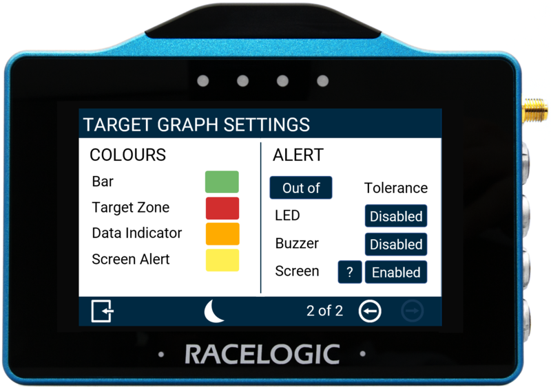
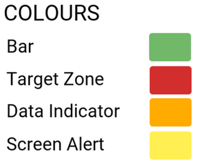
Colours Settings
Change the following colours in the Colours Settings.
- Bar
Set the colour of the bar in the background of the Target Graph. - Target Zone
Set the colour of the Target Zone in the Target Graph.
The Target Zone is configured in the Tolerance Value option in the Range settings. - Data Indicator
Set the colour of the Data Indicator on the Target Graph. This will indicate the current value. - Screen Alert
Set the colour of the Screen Alert that indicates when the Target Value Tolerance is met. You can find more information about changing this value in the Screen option in the Alerts settings below.
Change Alert Colour
Change a colour by tapping on the currently selected colour to open the relevant colour selection screen. Use the RGB sliders to define the required colour. The area to the left of the sliders provides a colour preview.
Save the new colour by tapping the Confirm button in the bottom right corner.
Tap the Cancel button in the bottom left corner to return the Settings Screen without saving.


NOTE
If you enable Night Mode, this will reset any user defined colours.
Alerts Settings
Tolerance
Configure whether the alert is for when a value is Out of (default) or Within the defined Target Value Tolerance. Tap the button to toggle between the options.

Configure whether the alert is for when a value is Out of (default) or Within the defined Target Value Tolerance. Tap the button to toggle between the options.

LED
The Visual Alert makes the LEDs either illuminate or flash when the Defined Target Value Tolerance is met.
Tap the button to toggle between the options.
VBOX Touch will preview an option as you set it.
The Visual Alert makes the LEDs either illuminate or flash when the Defined Target Value Tolerance is met.
Tap the button to toggle between the options.
VBOX Touch will preview an option as you set it.
Buzzer
Enable a sound alert (beep) when the Defined Target Value Tolerance is met.
Enable a sound alert (beep) when the Defined Target Value Tolerance is met.
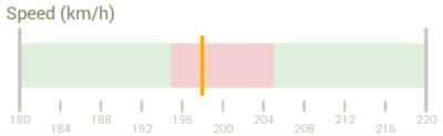
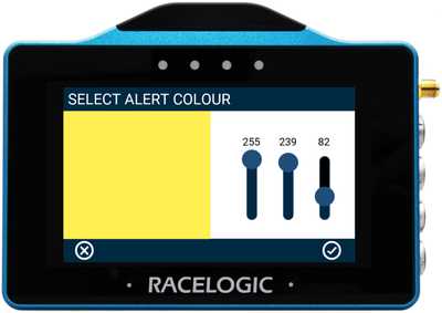
Screen
Enable a screen alert to display when the Defined Target Value Tolerance is met. Whenever the set target value zone is met, the Target Graph background will change colour.

Enable a screen alert to display when the Defined Target Value Tolerance is met. Whenever the set target value zone is met, the Target Graph background will change colour.
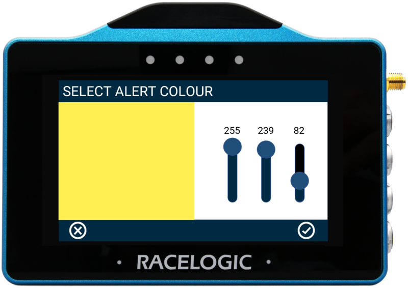
Change the background alert colour by tapping the current setting colour (yellow by default) to open the Select Alert Colour screen.
Use the RGB sliders to define the required colour. The area to the left of the sliders provides a colour preview.
Save a colour by tapping the Confirm button in the bottom right corner.
Tap the Cancel button in the bottom left corner to return to the Settings Screen without saving.
NOTES
- The setting will be greyed out and disabled if the numerical parameter you are configuring is UTC Time, Longitude or Latitude.
- If you enable Night Mode, any user-defined alert colours will be reset.
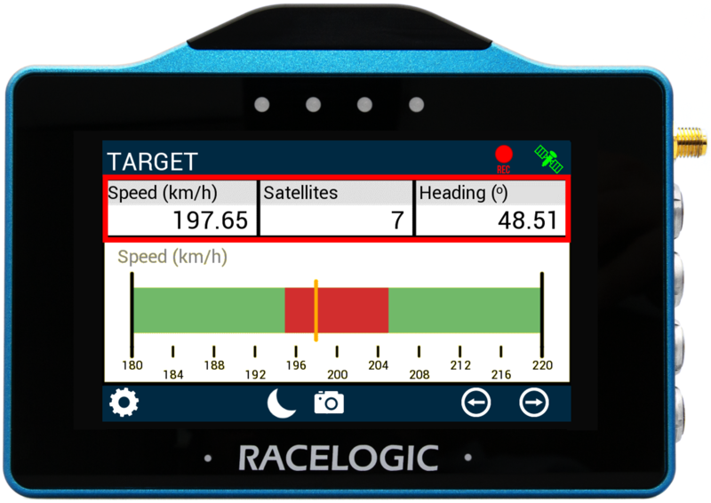
Numerical Elements
The 3 numerical elements are located on the top of the screen.
By default, they are Speed, Satellites and Heading.
Configure a parameter by either long-pressing or double-tapping the existing parameter to open the Numerical Settings menus.
Refer to the Numerical Settings in the Numerical Screens section above for more information about the available settings.
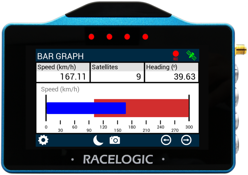
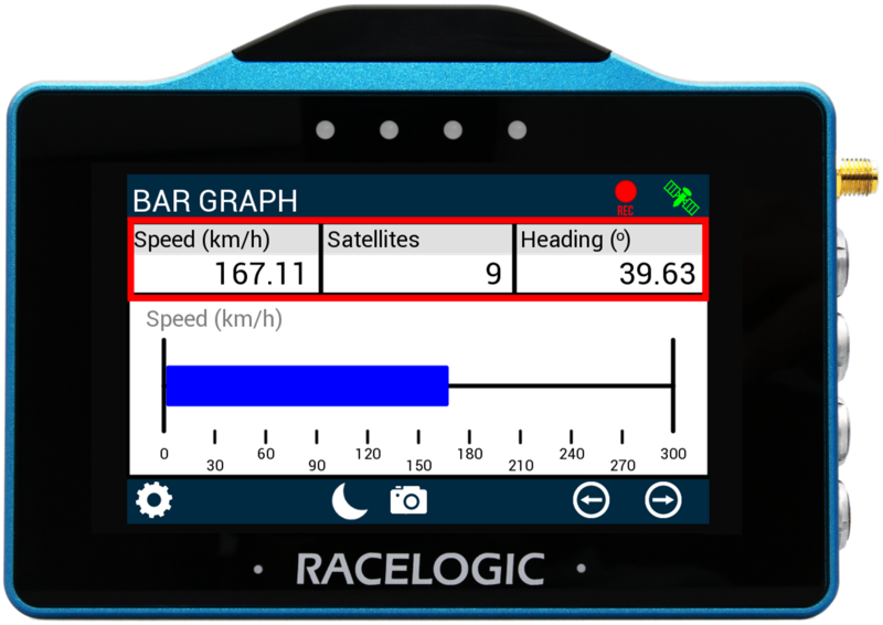
The Bar Graph screen contains a bar graph gauge with 3 supporting numerical elements. The applied units depend on what is selected in the VBOX Display Settings.
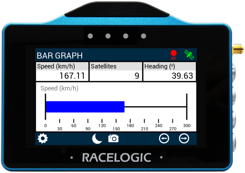
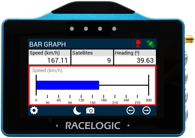
Bar Graph Element
The Bar Graph gauge element is located at the bottom of the screen and provides a visual representation of a selected parameter (by default, the parameter is set to Speed).
Configure the gauge element by either long-pressing or double-tapping on it to open the Bar Graph Settings.
There are two settings screens available, the Data/Range settings and the Alerts settings.
Use the Forward or Back arrows in the bottom right corner or swipe left or right on the the screen to move between the available screens.
Change a setting by tapping on the corresponding button next to an option.
Return to the parameter screen by tapping the Exit button in the bottom left corner.
NOTE
When an SD card is inserted, the settings values will be remembered after each power cycle.
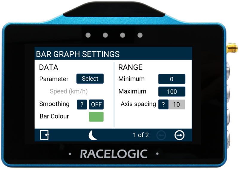
Bar Graph Settings - Data/Range
Data Settings
Parameter
The gauge parameter is set as Speed by default.
Change the parameter by tapping the Select button to open the parameter list.
You can assign any available data parameter from the connected VBOX to the Bar Graph Gauge (except UTC Time, Longitude or Latitude).
The gauge parameter is set as Speed by default.
Change the parameter by tapping the Select button to open the parameter list.
You can assign any available data parameter from the connected VBOX to the Bar Graph Gauge (except UTC Time, Longitude or Latitude).
NOTE
The currently selected parameter is displayed in grey beneath the option.
Use the scroll bar on the right hand side of the selection screen to navigate through the options and tap the required parameter to select it.
Return to the settings screen without saving by tapping the Exit button in the bottom left corner.
Smoothing
Apply smoothing to the Bar Graph data.
The value determines the number of previous data samples used to smooth the displayed data. It does not affect any of the performance results or the logged data of the connected unit.
Enable smoothing by tapping on the current value (set to Off by default) and use the presented keypad to enter the number of data samples you would like to use for the display smoothing.
Save the new value by tapping the Confirm button in the bottom right corner.
Tap the Cancel button in the bottom left corner to return to the Settings Screen without saving.
NOTES
- The maximum input value is 99.
- Smoothing can introduce a slight delay to the displayed value.
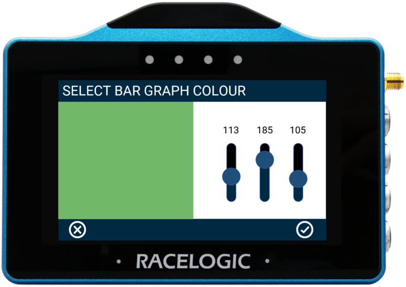
Bar Colour
Change the colour of the bar on the Bar Graph screen.
Tap the current colour (green by default) to open the Bar Graph Colour selection screen.
Use the RGB sliders to define your new colour. The area to the left of the sliders provides a colour preview.
Save the new colour by tapping the Confirm button in the bottom right corner.
Tap the Cancel button in the bottom left corner to return to the Settings Screen without saving.
NOTE
If you enable Night Mode, any user-defined bar colours will be reset.
Range Settings
Minimum/Maximum
Set the minimum and maximum range values for the axes of the Bar Graph element.
Change a value by tapping the button and using the presented keypad to enter the new value.
By default, the Minimum value is set to 0 and the Maximum value is set to 100.
Save the new value by tapping on the Confirm button in the bottom right corner of the screen.
Tap the Cancel button in the bottom left corner of the screen to return to the Settings Screen without saving.
NOTES
- The maximum input value is 99999.
- The minimum input value is -99999 (when a signed parameter is selected, otherwise 0).
- One decimal place resolution available.
Axis Spacing
The Axis Spacing setting displays the current spacing between each gauge increment marker on the Bar Graph.
This value depends on the set Minimum/Maximum Range.
The Axis Spacing setting displays the current spacing between each gauge increment marker on the Bar Graph.
This value depends on the set Minimum/Maximum Range.
Bar Graph Settings - Alerts
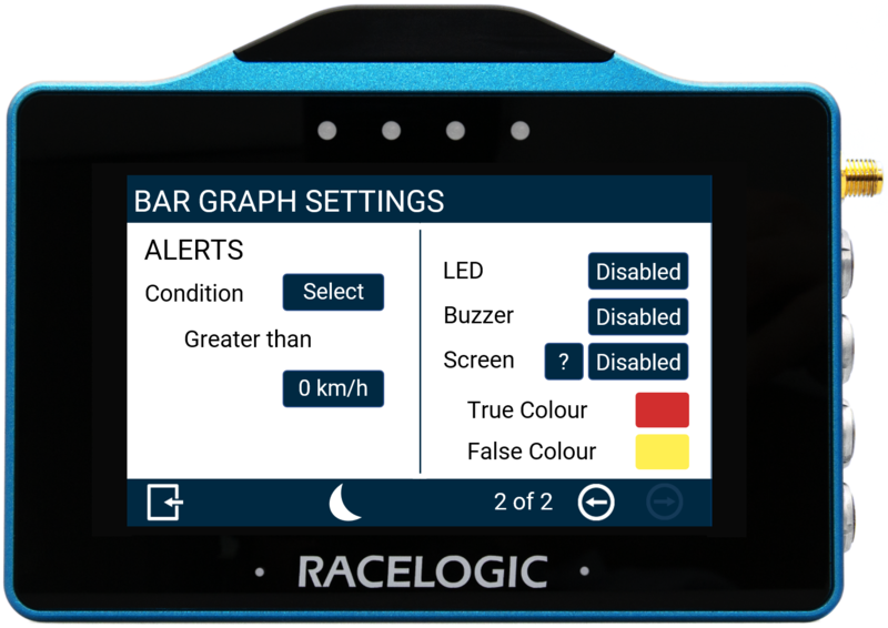
Condition
Define an alert condition by tapping the Select button to cycle through the available conditions:
- Equal To
- Not Equal To
- Less Than
- Less Than or Equal To
- Greater Than (default)
- Greater Than or Equal To
- Between
- Not Between
Set the condition value by tapping the value button and using the presented keypad to enter the required value.
Save the new values by tapping the Confirm button in the bottom right corner.
Tap the Cancel button in the bottom left corner to return to the Settings Screen without saving.
NOTE
The setting will be greyed out and disabled if the configured numerical parameter is UTC Time, Longitude or Latitude.
LED
Select to enable a solid or flashing visual alert when the Defined Alert Condition is met. Press the button to cycle through the options, the device will preview the setting with the 4 red LEDs across the top of the unit.
Select to enable a solid or flashing visual alert when the Defined Alert Condition is met. Press the button to cycle through the options, the device will preview the setting with the 4 red LEDs across the top of the unit.
Buzzer
Enable a sound alert (beep) for when the Defined Alert Condition is met.
Enable a sound alert (beep) for when the Defined Alert Condition is met.
Screen
Enable a screen target zone in relation to the defined Alert Condition. If is not yet achieved, the 'False Colour' will appear in the target zone. When the value is achieved, the 'True Colour' will appear in the target zone.
Change the True and False alert colours by tapping the current colours (yellow and red by default) to open the relevant colour selection screens. Use the RGB sliders to define the required colour. The area to the left of the sliders provides a colour preview.
Save the new colour by tapping the Confirm button in the bottom right corner.
Tap the Cancel button in the bottom left corner to return the Settings Screen without saving.
NOTE
If you enable Night Mode, this will reset any user defined alert colours.

Numerical Elements
The 3 numerical elements are located at the top of the screen and include Speed, Satellites and Heading by default.
Configure a parameter by either long-pressing or double-tapping the existing parameter to open the Numerical Settings menus.
Refer to the Numerical Settings in the Numerical Screens section above for more information about the available settings.
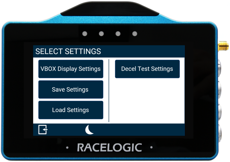
Access the MFD App Settings by tapping the Settings button in the bottom left corner.
This opens the Select Settings screen with the following options:
- VBOX Display Settings
- Decel Test Settings
- Save Settings
- Load Settings
Select an option by tapping on it.
Return to the parameter screen by tapping the Exit button in the bottom left corner
NOTE
If an SD card is inserted, settings values will be remembered after each power cycle.
The VBOX Display Settings consists of three different screens, two General Settings screens and a VBOX Information screen.
Use the Forward or Back arrows in the bottom right corner or swipe left or right the screen to move between the available screens.
Change a setting by tapping on the corresponding button next to an option.
Return to the Select Settings screen by tapping the Exit button in the bottom left corner.
General Settings - Units/Screen
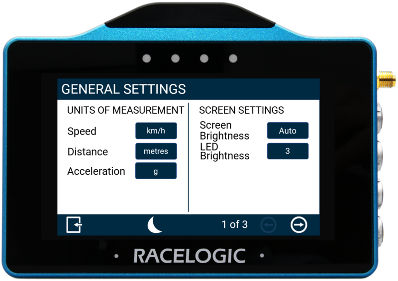
Units of Measurement Settings
Speed
Allows you to change the speed units between km/h (default) and mph. Changing the speed units will affect all visual speed parameters on all screens, the unit labels will change, and all speed values and results will automatically be recalculated. Tap the button to change the units.

Allows you to change the speed units between km/h (default) and mph. Changing the speed units will affect all visual speed parameters on all screens, the unit labels will change, and all speed values and results will automatically be recalculated. Tap the button to change the units.

Distance
Change the distance units used on the display. The option are metres (default) and feet.
Changing the distance unit will affect all visual distance parameters on all screens. The unit labels will change, and all distance values and results will automatically be recalculated.
Tap the button to change the units.

Acceleration
Allows you to change the acceleration units between g (default) and m/s². Changing the acceleration units will affect all acceleration references on all screens, the unit labels will change, and all acceleration values and results will automatically be recalculated. Tap the button to change the units.

Allows you to change the acceleration units between g (default) and m/s². Changing the acceleration units will affect all acceleration references on all screens, the unit labels will change, and all acceleration values and results will automatically be recalculated. Tap the button to change the units.

Screen Settings
Screen Brightness
Adjust the screen brightness manually.
1 is the dimmest and 5 is the brightest.
Auto (default) uses the internal ambient light sensor to automatically adjust the screen brightness. In dark conditions, the screen brightness will dim, and in light conditions, the screen will brighten.
Tap the button to cycle through the available options.

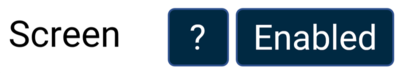
LED Brightness
Adjust the LED brightness manually.
1 is the dimmest and 5 is the brightest.
You can also turn the LEDs off by setting this option to Disabled.
Tap the button to cycle through the available options and the LEDs will preview the brightness level as you do.
The default brightness level is 3.

Adjust the LED brightness manually.
1 is the dimmest and 5 is the brightest.
You can also turn the LEDs off by setting this option to Disabled.
Tap the button to cycle through the available options and the LEDs will preview the brightness level as you do.
The default brightness level is 3.

CAUTION
LED brightness level 5 is very bright and may cause glare or discomfort in low-light conditions.
General Settings - Data/Alerts
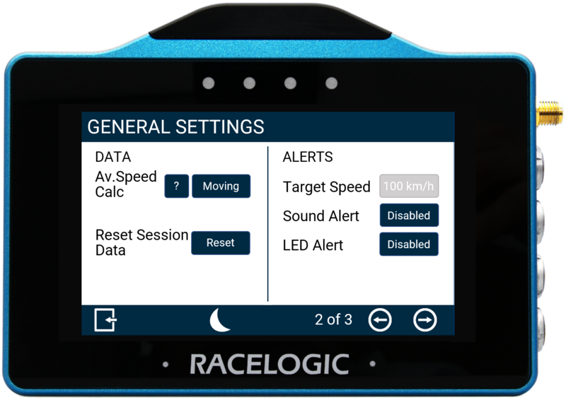
Data Settings
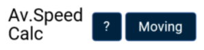
Av. Speed Calc
This setting determines how the average speed parameter data is calculated.
- Moving (default): Average speed will start to calculate as soon as a speed over 0.5 km/h is detected. Calculations will stop when the speed is less than 0.8 km/h.
- Continuous: Average speed is calculated continuously from the start of the test.
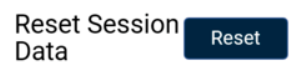
Reset Session Data
Tap this button to reset the results for the calculated average speed, maximum lateral acceleration and calculated distance travelled.
The LEDs will flash green and the unit will emit an audible confirmation notification.
VBOX Touch will display a Cancel Timeout screen, allowing you to cancel the reset within 5 seconds by tapping the screen.
If cancelled, the LEDs will flash red and the unit will emit an audible error note, notifying you that the reset has been cancelled.

Alerts Settings
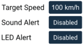
Target Speed
Define a Target Speed by tapping on the Target Speed button and using the presented keypad to enter the required speed (with up to 1 decimal place).
Save the target speed by tapping the Confirm button in the bottom right corner of the screen. Tap the Cancel button in the bottom left corner of the screen to return to the Speed Settings screen without saving the target speed. The value will be remembered after each power cycle.
The target speed will be displayed underneath the speed value on the Speed, VMAX and Average Speed screens.

NOTE
You can enter a speed value with up to 1 decimal place.
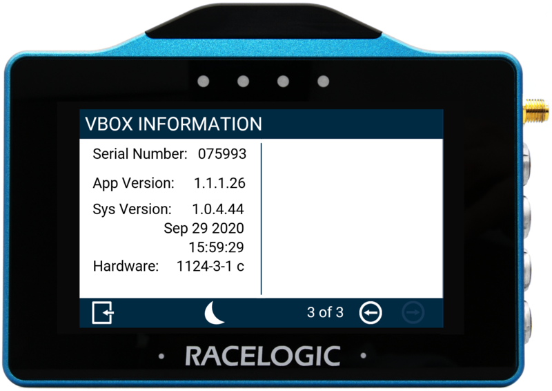
VBOX Information
The VBOX Information screen is the final screen in the VBOX Display Settings.
It displays the unit's serial number, the app version, firmware version number and hardware version number.
This information is useful in the event of troubleshooting a potential issue with the VBOX Touch device.
There are two Decel Test Settings screens.
The first settings screen (Decel Test Settings) is for conducting deceleration tests using start and end speed values, the second screen (Decel Test Settings - Trigger Only) is relevant when using a brake trigger.
Use the Forward or Back arrows in the bottom right corner or swipe left or right on the screen to move between the available screens.
Change the settings by tapping on the corresponding button next to an option.
Return to the Select Settings screen by tapping the Exit button in the bottom left corner.
You can view the parameters for the test on the display in the Decel Test parameters.
Decel Test Settings
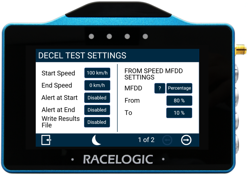
Start/End Speed
Define the start and end speed conditions of the deceleration test by tapping the corresponding buttons and using the presented keypad to enter the required speed values.

Define the start and end speed conditions of the deceleration test by tapping the corresponding buttons and using the presented keypad to enter the required speed values.
Alert at Start
Select to enable audible and visual alert signals when the decel test's start speed criteria are met. The unit will briefly beep and the 4 LEDs across the top of the device will flash green.

Select to enable audible and visual alert signals when the decel test's start speed criteria are met. The unit will briefly beep and the 4 LEDs across the top of the device will flash green.
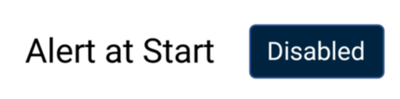
Alert at End
Select to enable audible and visual alert signals when the decel test's end speed criteria are met. The unit will beep and the 4 LEDs across the top of the device will flash green.

Select to enable audible and visual alert signals when the decel test's end speed criteria are met. The unit will beep and the 4 LEDs across the top of the device will flash green.
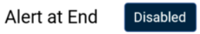
Write Results File
Select this option to enable the Decel Test results to be written to an inserted SD card.
If VBOX Touch cannot detect an SD card:
- the unit will beep
- the 4 LEDs across the top of the device will flash red
- the unit will emit an audible tone
- a 'NO SD CARD' message will display

Select this option to enable the Decel Test results to be written to an inserted SD card.
If VBOX Touch cannot detect an SD card:
- the unit will beep
- the 4 LEDs across the top of the device will flash red
- the unit will emit an audible tone
- a 'NO SD CARD' message will display
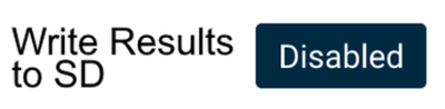
From Speed MFDD Settings
This area allows you to set up the start and end periods of the Mean Fully Developed Deceleration (MFDD) analysis period.
This deceleration figure is used to show the maximum deceleration figure a vehicle can achieve. It is usually the deceleration between 80% and 10% of the trigger activation speed, the time at which the vehicle is loaded up and braking at its highest achievable level.
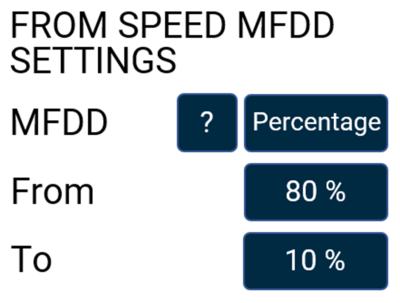

Refer to the VBOX Touch User Guide for more information about MFDD.
Decel Test Settings - Trigger Only
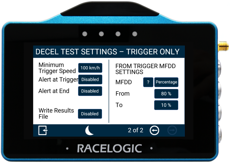
Minimum Trigger Speed
Define the minimum trigger speed at which trigger activation becomes valid. If the trigger is detected below this speed, the test will not start.
Change this value by pressing the current value and using the presented keypad.

Define the minimum trigger speed at which trigger activation becomes valid. If the trigger is detected below this speed, the test will not start.
Change this value by pressing the current value and using the presented keypad.
Alert at Trigger
Select to enable audible and visual alert signals when the decel test's trigger test has started. The unit will briefly beep and the 4 LEDs across the top of the device will flash green.

Select to enable audible and visual alert signals when the decel test's trigger test has started. The unit will briefly beep and the 4 LEDs across the top of the device will flash green.
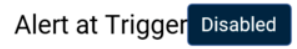
Alert at End
Select to enable audible and visual alert signals when the decel test's end speed criteria are met. The unit will beep and the 4 LEDs across the top of the device will flash green.
Select to enable audible and visual alert signals when the decel test's end speed criteria are met. The unit will beep and the 4 LEDs across the top of the device will flash green.
Write Results File
Select this option to enable the Decel Test results to be written to an inserted SD card.
If VBOX Touch cannot detect an SD card:
- the unit will beep
- the 4 LEDs across the top of the device will flash red
- the unit will emit an audible tone
- a 'NO SD CARD' message will display
Select this option to enable the Decel Test results to be written to an inserted SD card.
If VBOX Touch cannot detect an SD card:
- the unit will beep
- the 4 LEDs across the top of the device will flash red
- the unit will emit an audible tone
- a 'NO SD CARD' message will display
From Trigger MFDD Settings
This area allows you to set up the start and end periods of the Mean Fully Developed Deceleration (MFDD) analysis period.
This deceleration figure is used to show the maximum deceleration figure a vehicle can achieve. It is usually the deceleration between 80% and 10% of the trigger activation speed, the time at which the vehicle is loaded up and braking at its highest achievable level.
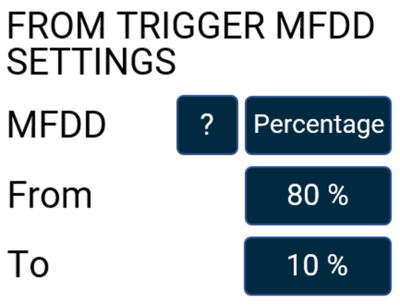

Refer to the VBOX Touch User Guide for more information about MFDD.
To save the settings to an inserted SD card, select the 'Save Settings' button and enter a suitable file name using the presented keyboard. To save the name, press the Confirm Button on the bottom right of the screen, or press the Cancel Button on the bottom left of the screen to return the Settings screen without saving.
The button will be greyed out if an SD card is not detected.
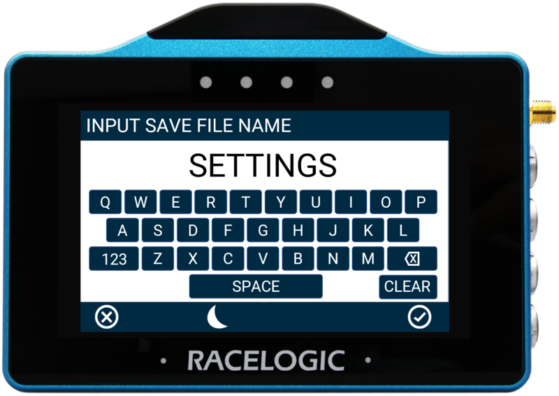
If confirmed, the screen will present a file saved notification, the LEDs will flash green and the unit will emit an audible confirmation notification.
If a settings file with the same name already exists on the SD card, the unit will advise that the file is being overwritten, a cancel timeout screen will display, allowing you to cancel the overwriting process within 5 seconds by pressing the screen.
If cancelled, the LEDs will briefly flash red and the unit will emit an audible tone, notifying you that the overwriting has been cancelled.
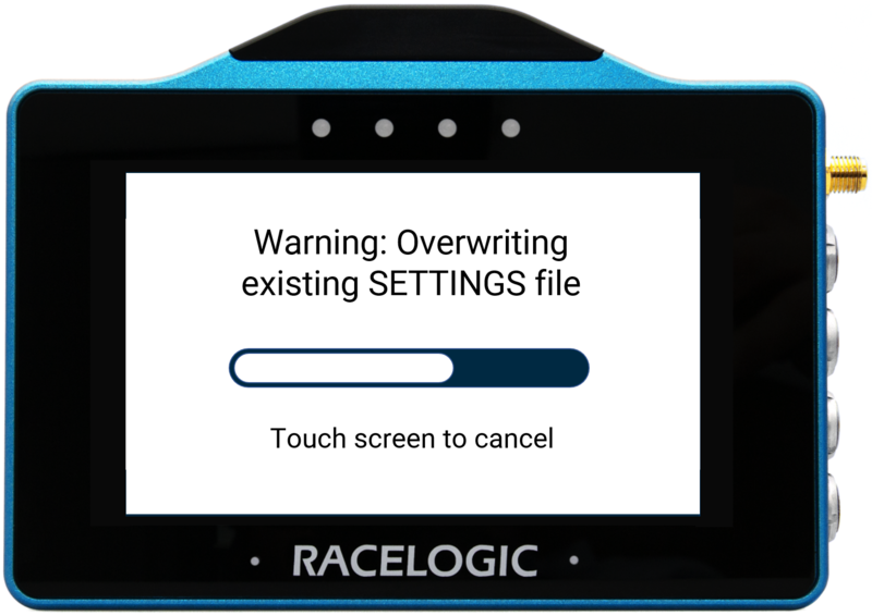
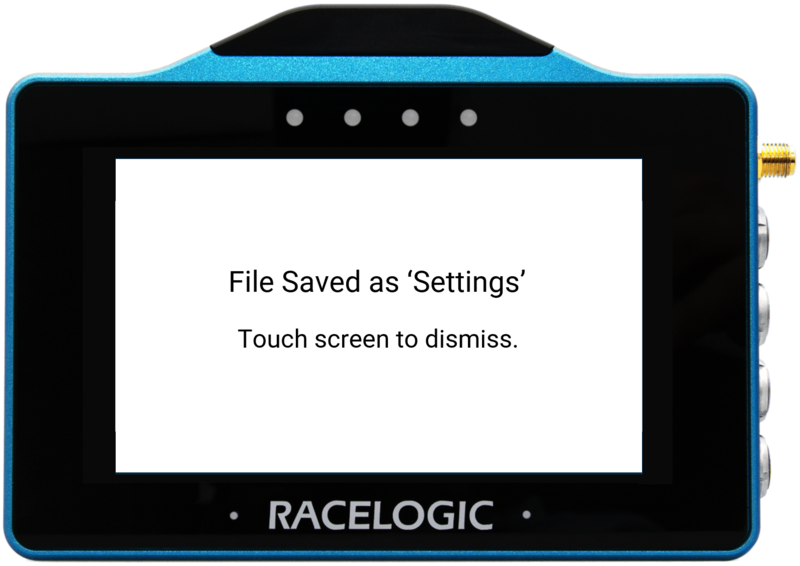
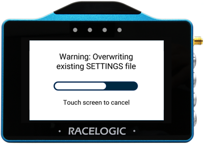
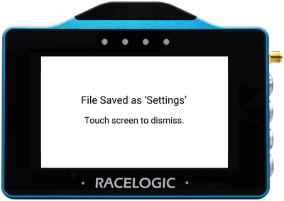
To load a previously saved settings file from an inserted SD card, press the Load Settings button. The unit will present all the available settings files that are located on the SD card. Tap on the desired file and then press the Confirm button at the bottom right of the screen to load it. Press the Cancel button at the bottom left of the screen to return the Settings screen without saving. If you press confirmed, the screen will present a 'file loaded' notification, the LEDs will flash green and the unit will emit an audible confirmation notification.
NOTE
The button will be greyed out if the unit cannot detect an SD card.
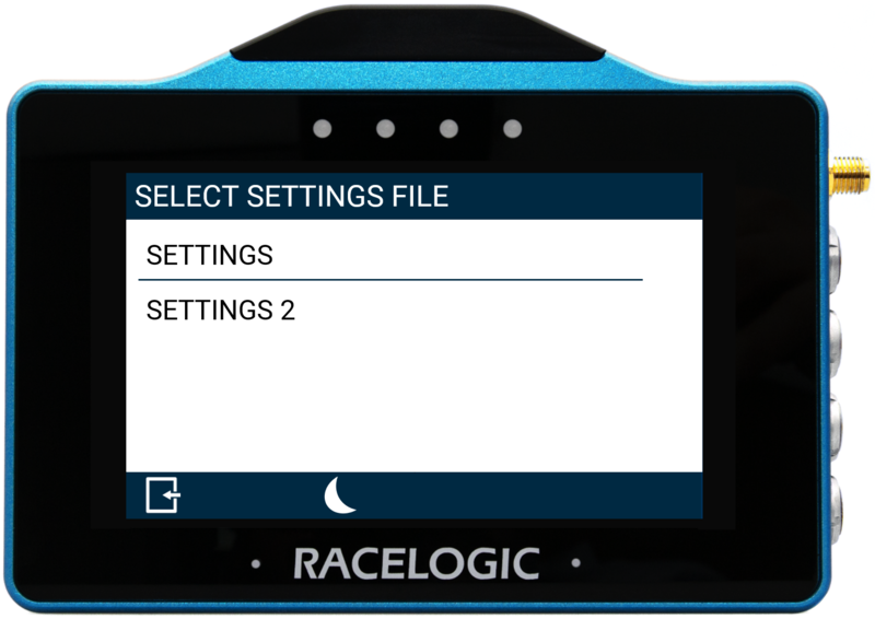
The app supports performance and deceleration testing using data from the connected VBOX.
Some test features require additional hardware, such as a brake trigger or pedal force sensor.
For full details on test configuration and operation, refer to the MFD Touch User Guide.
The currently installed app determines the CAN output behaviour of VBOX Touch.
When using the MFD App, VBOX Touch outputs CAN data consistent with the MFD Touch product, rather than its standard VBOX Touch CAN output. This includes performance test results and parameter data generated by the app.
CAN output is available via the VBOX Touch CAN/Serial ports.
For full details of CAN message structure, channel definitions, and scaling, refer to the VBOX Touch CAN Output page.
Before running a test, make sure that the system is correctly configured and configure the VBOX Touch MFD App:
- Connect VBOX Touch to the VBOX using the RLCAB005-C cable.
- Configure the Display Settings (Settings → VBOX Display Settings)
- Add the required data display screens.
- Configure the data display screens as required (refer to the Data Displays section for more information about the available settings for each display element).
The MFD App does not run tests itself, but displays live test data and results from a compatible and connected VBOX unit. It enables the users to monitor test progress and view calculated results in real time.
You can, however, control the logging on the connected VBOX unit via the MFD App on VBOX Touch.
The logging state is indicated by the Logging Status icon and on-screen messages.
Red Media Status Icon
If the recording media is unavailable or full, VBOX Touch will cancel the logging command and display one of the following error messages:
- NO MEDIA AVAILABLE - No detected recordable media.
- CARD FULL - Media detected but no logging capacity remains.
- NO MEDIA AVAILABLE - VBOX is unable to write to recordable media (i.e. corrupt card).
Green Media Status Icon
When VBOX Touch has detected available recording media on the connected VBOX unit, you can control the logging by tapping on the Logging Status icon.
If the VBOX has been configured to log when moving, the system may display an ARMED state while waiting for the required conditions to start logging.