VBOX Video HD2 has the ability to show on-screen lap times, as well as on a connected OLED display.
By default, the HD2 system is set up to use automatic track recognition. This feature allows the HD2 to search through a built in circuit database of over 500 circuits and load all layouts from the detected GPS location.
To check the version number of the track map database that is installed, select 'Help' → 'Check For Updates' within VBOX Video Setup.
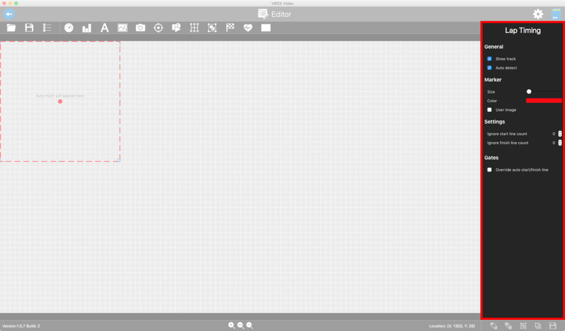
To add an automatic track map element, click on the 'Lap Timing' icon from the top panel buttons menu.

This will load a lap timing element into the software. This element can be clicked and dragged into the desired location in the scene.
The VBOX Video HD2 system will now automatically load a track map image and start/finish line based on detected GPS location – in order to have full control over circuits with multiple layouts present, an OLED display is needed.
Click here for more information on using automatic track recognition with an OLED.
NOTE
Auto track map elements cannot be resized as the PNG images for each track are built into the internal firmware.
If multiple tracks are found for the current location and no OLED display is at hand the track map will default to:
- The last matching track that the user selected previously at that location.
- The first matching ‘combo’ map (if option 1 is not possible).
- The first track alphabetically on the list (if option 1 and 2 are not possible).
When the track map element is selected, the settings for this will be shown in the right-hand panel.
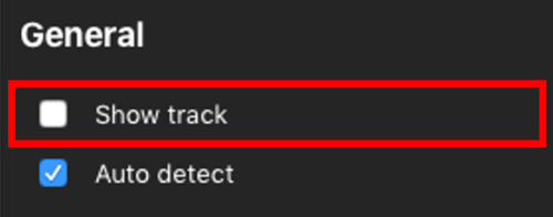
To have the start/finish line automatically detected without any map image shown in the video overlay, simply untick the ‘Show track’ box. The map will vanish from the scene view when this is done.
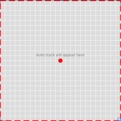
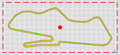
By default, the VBOX Video HD2 will show a red dot as a positional marker on the track map.
The colour of this can be changed by selecting the existing colour and choosing from the colour wheel. The opacity of the colours can also be changed here. To set a specific RGB value, click ‘Color sliders’.
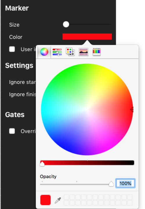
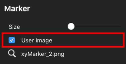
Additionally, there is an option to load a user image. To do this, tick the ‘User image’ box, and click the search icon to load a PNG/BMP/GIF or JPEG image file.
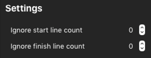
In situations where the start line will be crossed before lap timing should start, a value of 1 (or more) can be entered into the ‘Ignore start line count’ box.
Equally, for some sprint races, two physical laps are taken into account to produce one lap time. The ‘Ignore finish line count’ box can be used to stop the VBOX Video reacting when the finish line is crossed.
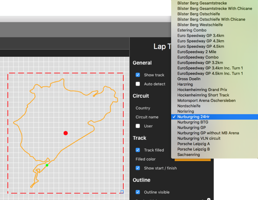
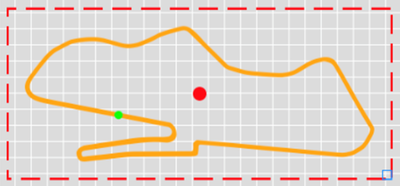
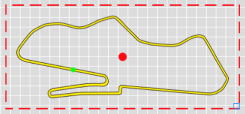
Fixed track maps are for use in a single location, as the track will not change automatically. Fixed track maps can be resized and have colour settings for fill and outline changed to suit the scene design.
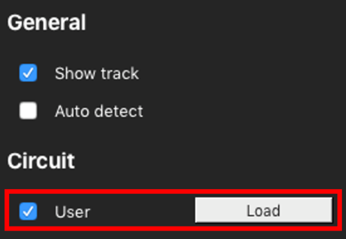
To load a fixed track map into the software, untick the ‘Auto detect’ box. This will cause a map image to appear in the scene – select the desired map layout from the ‘country’ and ‘circuit’ drop-down boxes.
NOTE
For Lap timing to work at another location, the user will have to change the circuit manually and load a new scene into the VBOX Video HD2.
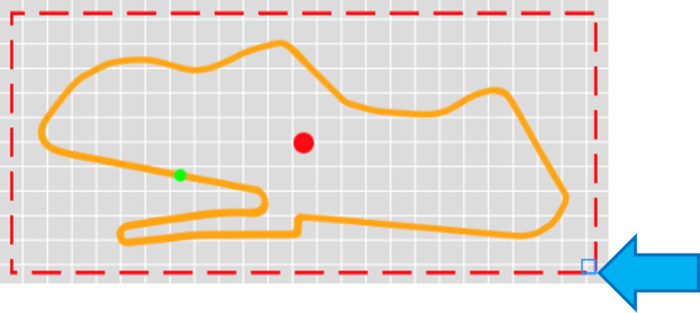
To resize a fixed map, click and drag the icon in the bottom right hand corner of the element.
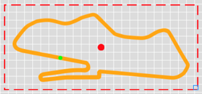
To change the colour of the circuit outline, or fill colour, use the two drop down boxes in the right hand panel.
To set a specific RGB value, click ‘Color sliders’.


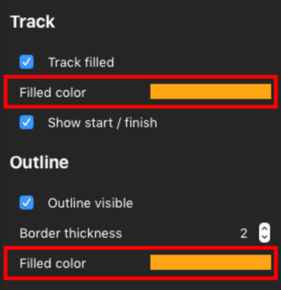
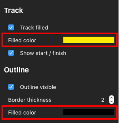

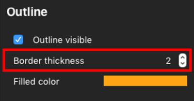
To change the thickness of the displayed track, use the arrow buttons to change the ‘Border thickness’ setting.


If a track is not present in our database, this can be created either from a logged VBO data file, or by drawing the circuit layout in Google Earth.
To load a user-defined track, tick the ‘User’ box under the country selection and press ‘Load’.
If a start/finish line is not present in our database, this can be created either from a logged VBO data file, saved out from the start/finish wizard in Circuit Tools software, or by creating start/finish lines in Google Earth.
To load a user-defined start/finish line, tick ‘Override auto start/finish line’ under ‘Gates’. This will cause new buttons to appear – clicking on ‘Load’ will allow a splits file to be loaded.
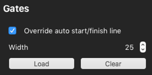
The Gate width option appears if you are not using the start/finish lines from our database. It controls how wide the start/finish line is across the track. The default setting for this is 25 m.
When racing at a very narrow circuit where the pit lane is right next to the start line, it could be possible to trigger lap timing within the pit lane. To change this setting, use the up and down arrow boxes or key in a value.
The drawing below shows how the gate width setting affects the start/finish line.