The CAN menu contains settings for selecting channels, CAN inputs and CAN bus settings.
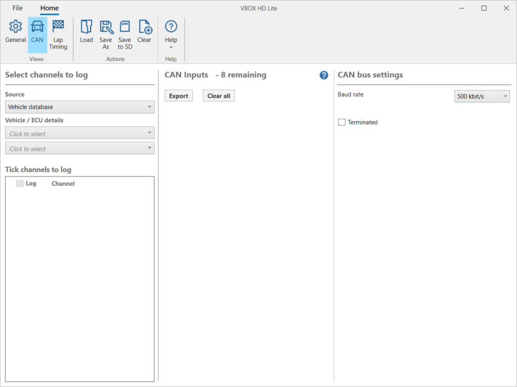
This area lets you choose the source and type you are using for your CAN channels.
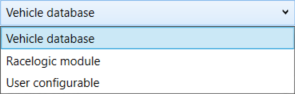
You have 3 source options for the CAN channels:
Vehicle database (default)
The Racelogic Vehicle CAN Database contains hundreds of different signals for many different makes and models of vehicles.
Racelogic module
You can log data from other Racelogic modules, such as ADC, IMU, YAW, FIM and TC modules.
User configurable
This will cause a button to appear labeled ‘Load database’. Select this button to load your own CAN database file (.REF, .DBC, .VCI). The channels will then appear for you to select.

NOTE
In order to communicate with Video VBOX units, Racelogic modules must be set into Timed CAN mode. For more information on how to do this, please see the user guide for the module in use.
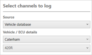
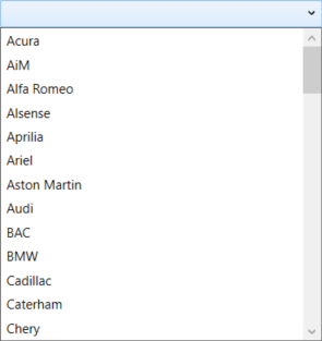
When you have selected Vehicle database as your source, you can click on the Vehicle/ECU details dropdown menus to see lists of the available vehicle makes and models and select the one that applies to you.

When you have selected Vehicle database as your source, you can click on the Vehicle/ECU details dropdown menus to see lists of the available vehicle makes and models and select the one that applies to you.
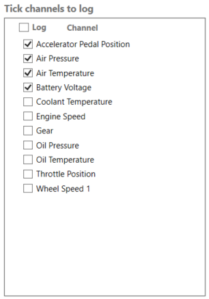
After selecting the Source, you will see a list of available channels you can log. Tick the tick box for a channel to select it.

After selecting the Source, you will see a list of available channels you can log. Tick the tick box for a channel to select it.
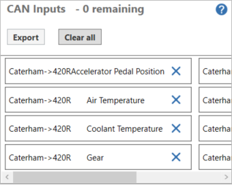
This area will display the selected inputs along with the remaining available inputs.
You can click on the Export button to export a .ref file containing the selected channels.
Click Clear all to remove all selected inputs.

This area will display the selected inputs along with the remaining available inputs.
You can click on the Export button to export a .ref file containing the selected channels.
Click Clear all to remove all selected inputs.
Click on an input in the CAN Inputs area to open the settings for the input.
This area gives you the option to rename a selected channel or to change its units.
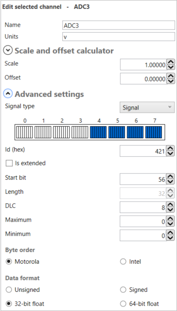
This area lets you apply scale (multiplier) and offset (add or subtract) values to convert the data into a more meaningful format.
- Signal - Normal message
- Multiplexor - multiplexor message
(The HD Lite supports up to 2 multiplexor signals) - Multiplexed - multiplexed message
(The HD Lite supports up to 8 multiplexed CAN messages)
If you do configure a multiplexor message then another 2 fields will appear:
- Multiplexor signal – choose the multiplexor message that you defined earlier.
- Multiplexor – Value
The individual bit where the CAN message begins.
The length of the CAN message.
Data length code - Length of the data in the CAN message.
The maximum and minimum values.
You can select the byte order that is applicable to your test. Your options are:
- Motorola - Big Endian
- Intel - Little Endian
You can select the data format you wish to use. Your options are:
- Unsigned - Raw integer
- Signed - Integer is either positive or negative
- 32-bit float - 32-bit message
- 64-bit float - 64-bit message
- Pseudo signed - magnitude integer
If it is available, the software will provide you with CAN connection information for the vehicle you have selected.

If it is available, the software will provide you with CAN connection information for the vehicle you have selected.

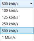
You can change the CAN baud rate in this area. The default baud rate is 500 kbit/s, but you also have the following options:
- 100 kbit/s
- 125 kbit/s
- 250 kbit/s
- 500 kbit/s (default)
- 1 Mbit/s


You can change the CAN baud rate in this area. The default baud rate is 500 kbit/s, but you also have the following options:
- 100 kbit/s
- 125 kbit/s
- 250 kbit/s
- 500 kbit/s (default)
- 1 Mbit/s
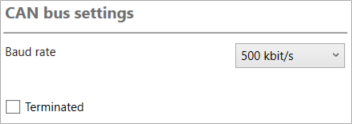
The VBOX HD Lite contains an active termination between 0 Ohms and 120 Ohms. You can enable/disable the CAN termination by ticking or unticking this setting box. This is disabled by default.