This page provides a detailed history of firmware versions for the VBOX Touch, including the features, behaviour, and user interface associated with each version.
For each firmware version, you can find:
- New and updated features
- Changes to behaviour and functionality
- How the user interface looks and operates in that version
This information can be used to understand version-specific behaviour or to compare how the product has changed over time.
Detailed user interface and behaviour information is available from firmware version v1.4 onwards. Earlier versions include summary release information only.
This is the initial release of CAN functionality on VBOX Touch. It adds support for CAN input (from vehicle database/DBC files or RACELOGIC modules) and CAN output.
CAN Bus
The CAN Bus menu is where you configure the settings for your CAN data capture. The menu is split into two sub-menus, one for each isolated CAN port on the VBOX Touch unit.
You can set each port to one of the following modes: CAN input, Racelogic (RL) modules or CAN output. When you set it to CAN output, VBOX Touch will be transmitting its own GNSS-derived data, including lap timing data, to a third-party CAN logger.
CAUTION
Connect to the vehicle CAN bus at your own risk.
CAN Settings
Select CAN BUS from the available settings screens:
Your first option is to select which port you want to configure the CAN settings for. Use the Forward and Back arrows in the bottom right-hand corner to navigate between the two ports and their settings. The settings options are the same for both the top and bottom port.
CAN Mode
This setting lets you choose which CAN mode you want to use for this port. You can choose between RL Modules, Input, Output and Disabled. Press on the '?' to see an overview and an explanation of the different CAN modes available.
When you have selected the CAN mode you want to use, you will get the option to configure the selected mode. Press the Configure button that appears below your CAN Mode selection.
RL Modules
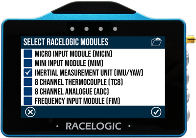
When you select to configure the input from an Racelogic Module (RL Module), you must first select the RL modules you are connecting to VBOX Touch.
You have 6 available modules and can choose to connect to one or more. Select them by pressing the respective tick boxes on the left-hand side and pressing the Confirm button to confirm your selection.
Press the Cancel button if you want to return to the CAN Mode screen without saving.
When you are using RL modules, you have to set them to Timed CAN mode with default output message identifiers. You must do this in VBOX Setup before you start logging.
NOTES
- You can find configuration files for compatibility with the VBOX Touch RL MODULES mode on the Automotive Website for quick configuration.
- Follow the link and click on the Modules tab.
- Scroll down until you see RACELOGIC Module configuration files for use with VBOX Touch and click Download.
- You can upload the appropriate file to the module via the VBOX Setup software.
- Make sure that the termination is set to enabled when you are capturing module data.
- If you want to capture data from multiple modules of one type, such as two IMU modules, you must either separate the capture across the two ports or use Input mode. If you are using more than two modules, you will have to use the Input mode and set the modules up in a daisy chain. You can find more information about this under Input Modules under the Input section below.
Input
When you select to configure the port to capture CAN Input, you will first have to select which database you are using to decode incoming data.
You will get a list of options and can either choose the internal vehicle CAN database or you can load external DBC files from the SD card onto the unit to select from.
To use the internal vehicle database, choose Select from the vehicle CAN database. This will give you a list of available channels with a comprehensive list of makes and models. Select the channels you wish to log by pressing the respective tick boxes on the left-hand side and pressing the Confirm button to confirm your selection.
Press the Exit button if you want to return to the CAN Mode screen without saving.
![VBOX Touch displaying the Select Channels to Log screen with a list of available Alfa Romeo/147 [Type 937] channels.](https://projecteinsteinstorage.blob.core.windows.net/media/production/images/VBOX_TOUCH_TEMPLATE_FW_v1.5_-_Input_Modules_Sel.original.png)
When you select to configure the port to capture CAN Input, you will first have to select which database you are using to decode incoming data.
You will get a list of options and can either choose the internal vehicle CAN database or you can load external DBC files from the SD card onto the unit to select from.
To use the internal vehicle database, choose Select from the vehicle CAN database. This will give you a list of available channels with a comprehensive list of makes and models. Select the channels you wish to log by pressing the respective tick boxes on the left-hand side and pressing the Confirm button to confirm your selection.
Press the Exit button if you want to return to the CAN Mode screen without saving.
![VBOX Touch displaying the Select Channels to Log screen with a list of available Alfa Romeo/147 [Type 937] channels.](https://projecteinsteinstorage.blob.core.windows.net/media/production/images/VBOX_TOUCH_TEMPLATE_FW_v1.5_-_Input_Modules_Se.width-400.png)
NOTES
- The Internal CAN database must be loaded onto the unit before you can use it. The database is a separate upgrade file that is included in the firmware download.
- There is a limit of 64 logged CAN channels, applied across both CAN ports.
- You must make sure that the Baud rate and termination settings match your expected connection.
Input Modules
You can use Input mode to capture single or multiple CAN modules or if you need to capture multiple RL modules of the same type (in a daisy chain).
When setting up a daisy chain, you must:
- Set the modules to Timed mode.
- Change the default output identifiers for each added unit of that type (to something unique).
- Construct or load your own (singular) database file that has channels for all the modules you are connecting to.
After confirming the modules you want to use, you will see the Input Modules screen. This screen is split into halves, with your selected modules on the left-hand side and the logged channels on the right-hand side.
Tap on one of the channels on the right-hand side to edit it.
Logged Channels
When you have confirmed the modules you want to use, the Input Modules screen will be displayed. This screen is split into halves, with your selected modules on the left-hand side and the logged channels on the right-hand side.
Tap on one of the channels on the right-hand side to edit it.
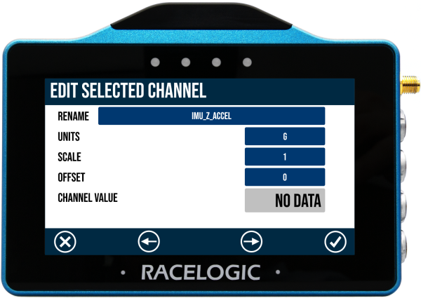
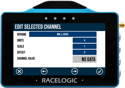
Edit Selected Channel
This settings screen has relevant information for the selected channel. You can configure the name, units, scale, and offset, and you can see the channel value if it is connected and transmitting data.
Use the forward and back buttons to navigate to the previous or next available channel.
Press the Confirm button to confirm your edits and go back to Input modules.
Depending on the selected module, you may get the option to calculate the scale and offset. When you select one of the following modules, you will see a CALC button next to the scale and offset values.
- Micro Input Module (MICIN) - all channels
- Mini Input Module (MIM) - analogue channels only
- Analogue to digital (ADC03) - all channels
Press the CALC button to open the Scale and offset calculator.
After you have configured your channels, you will see that the Configure button in the CAN settings has changed to Edit. Press Edit to see the channels you have configured to log. If you want to make a change to the configured channels, press the Change Selection button at the bottom of the screen.
You can now add or remove the channels in the currently selected database, or you can press Change Database to choose a different database to select channels from.
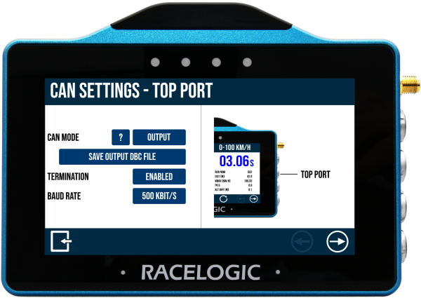
Output
Both ports have the ability to output GNSS and Lap Timing CAN data from the VBOX Touch. You can export and save the CAN database (to decode) directly from the unit to the SD card, by using the Save Output DBC file function. This option will be available when you select Output as your CAN mode.
Termination & Baud Rate
In addition to selecting the CAN mode and the logging channels, you can also Disable/Enable Termination and set the Baud Rate.
NOTE
When you are using the internal CAN database, termination and baud rate will be set automatically.
If, at any point, you have any questions or issues regarding CAN capturing on VBOX Touch, please contact Racelogic Support.
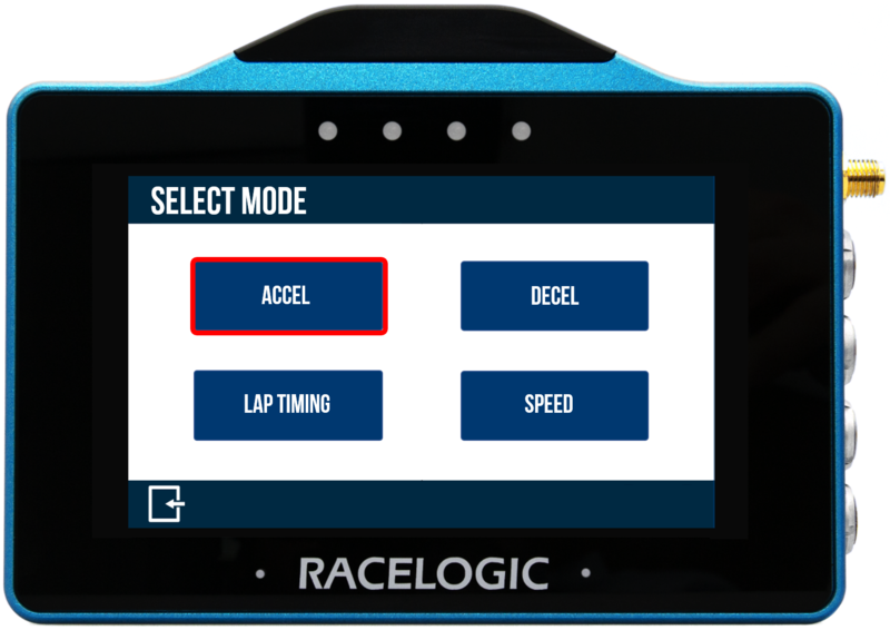
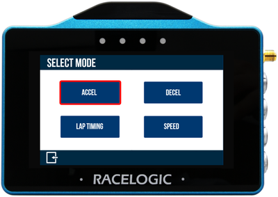
The Acceleration Mode allows you to perform acceleration tests using pre-defined configurations, or using your own specified values. It is also possible to display up to 4 concurrent test results on the screen. It is accessed by pressing the Mode Button at the bottom of the screen and selecting Accel.
The last selected Acceleration test will be displayed after each power cycle. It is possible to choose from either Speed or Distance parameters to start and end the test. Test results displayed on the screen of the VBOX Touch will remain on screen at the end of the test until the next start condition is met.
Speed units used are dependent on what is selected in the General Settings area.
NOTE
If the start condition is 0 km/h, VBOX Touch will use the Smoothed Speed Value to reset the test to avoid a test incorrectly resetting within noisy satellite reception areas.
Accel Mode Overview
There are 3 different Acceleration screens. You can navigate between with the Forward and Back arrows on the bottom right of the screen or by swiping the screen left or right.
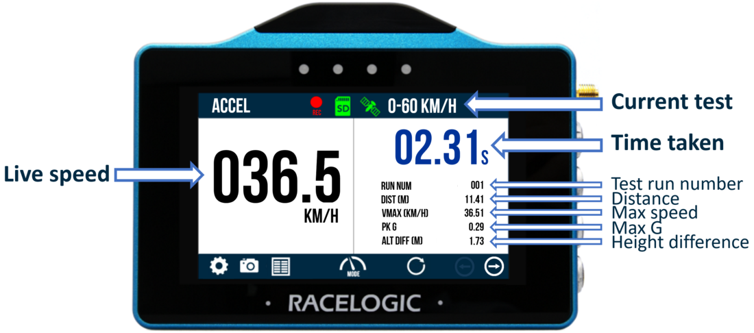
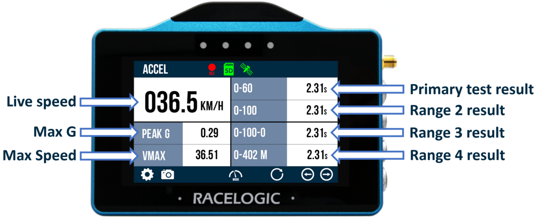
Primary Screen
This is the default acceleration screen and displays current/completed test information. If One Foot Rollout or Slope Correction is enabled within the Accel Settings, the test header text will reflect the options.
The screen is split in two halves:
- Left hand side: This includes a live speed display which will always show the current speed of the vehicle, irrespective of any test start or end conditions. If the vehicle is traveling less than 0.5 km/h or satellite lock is lost (less than 4 sats), the value will display as 000.0.
- Right hand side: This contains test information: time taken, run number, distance travelled, maximum speed achieved (Vmax), maximum acceleration achieved (g) and height difference. These values will start to populate once the start condition of the test is met. When the end condition is met, they will remain on screen until the start condition is met again. A test can be reset by pressing the Reset button at the bottom of the screen.
Secondary Screen
This screen displays current test information for all ranges. If One Foot Rollout or Slope Correction is enabled within the Accel Settings, the test header text will reflect the options.
The screen is split in two halves:
- Left hand side: This includes a live speed display which will always show the current speed of the vehicle, irrespective of any test start or end conditions. If the vehicle is traveling less than 0.5 km/h or satellite lock is lost (less than 4 sats), the value will display as 000.0. Maximum acceleration achieved (Peak G) and maximum speed achieved (Vmax) information is also available. These values will start to populate once the start condition of the Primary test is met. When the end condition is met, they will remain on screen until the start condition is met again. A test can be reset by pressing the Reset button at the bottom of the screen.
- Right hand side: This contains results from the defined acceleration test ranges, either as time, distance or speed. These values will start to populate once the start condition of the test is met. When the end condition is met, they will remain on screen until the start condition is met again. Along with pressing the Settings button, Accel tests can also be defined by double tapping on an existing test range header or result.
You can reset a test by pressing the Reset button at the bottom of the screen.
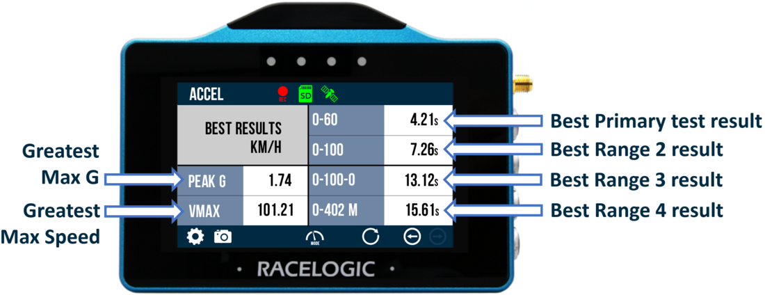
Best Result Screen
This screen displays best test information for all ranges. If One Foot Rollout or Slope Correction is enabled within the Accel Settings, the test header text will reflect the options.
The screen is split in two halves:
- Left hand side: This includes the maximum acceleration achieved (Peak G) and maximum speed achieved (Vmax) since reset. These values can be reset by pressing the Reset button at the bottom of the screen.
- Right hand side: This contains the best results from the defined acceleration test ranges, either as time, distance or speed. These values can be reset by pressing the Reset button at the bottom of the screen.
We have added an option to ignore double-distance laps in Lap Timing Mode. It is disabled by default.
When Disabled, a new reference lap will be created if the lap distance is more than double the stored reference lap. This can, for example, be useful if you are warming up on a smaller part of a longer circuit (for example the Nurburgring circuit and Nordschleife) and you want the reference lap to update once you have moved on to the longer circuit.
When Enabled, the reference lap will not update when the lap distance is more than double the distance of the stored reference lap. This can, for example, be useful when the in-lap may cover more than double the distance of the reference lap.

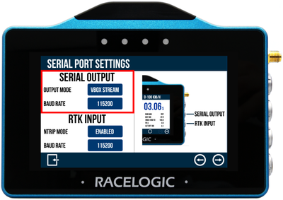
Serial output is available on the top CAN/Serial port on the VBOX Touch, illustrated in the image added on the right side of the Serial Port Settings screen.

Serial output is available on the top CAN/Serial port on the VBOX Touch, illustrated in the image added on the right side of the Serial Port Settings screen.
Output Mode
If required, choose the output mode of the serial port. Your options are VBOX Stream, Lap Timing or Disabled (default).
VBOX Stream allows you to connect VBOX Touch with a computer using an RLCAB001 and conduct online testing with VBOX Test Suite.
The Lap Timing option will output lap timing parameters.
Baud Rate
Displays the serial output baud rate, set as 115200 kbit/s.

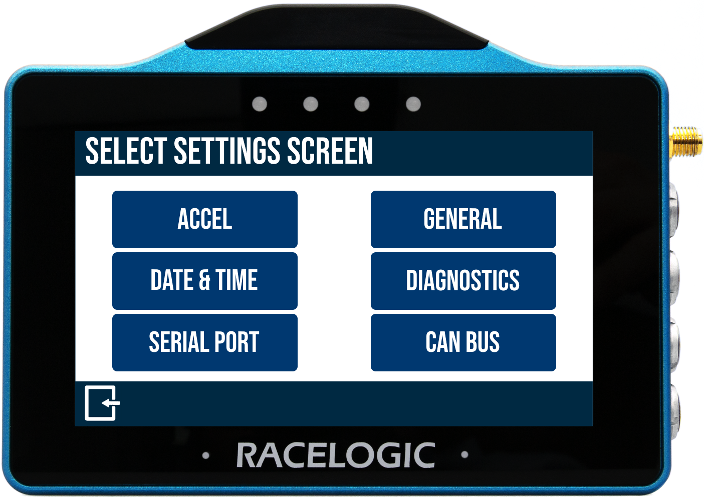
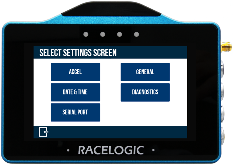
The Settings Button in the bottom left of the display mode screens will open the Select Settings Screen, where you can select the settings menu you want to access.

The Settings Button in the bottom left of the display mode screens will open the Select Settings Screen, where you can select the settings menu you want to access.
The options are Display Mode settings, General settings, Date & Time settings, Diagnostics settings and Serial Port settings.
The Display Mode settings available on the Select Settings Screen depend on which Display Mode you are using.
Once within a menu, other settings can be accessed by selecting the Forward and Back arrows on the bottom right of the screen or by swiping the screen left or right. Settings can be changed by pressing the corresponding button next to an option.
Return to the Select Settings Screen by tapping the Exit button in the bottom left corner. Tap it again to return to the current Display Mode screen.
Mode Settings
The display mode setting (Accel, Decel, Lap Timing, or Speed) available on the Select Settings Screen depends on the selected display mode.
Accel
The Accel Settings is where you select the test parameters and manage other test options. You can change settings by tapping on the corresponding button next to an option.
Return to the Accel Mode screen, by tapping on the Exit button in the bottom left corner.
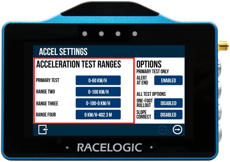
Acceleration Test Ranges
You can define four concurrent tests. By default, these are 0–60, 0–100, 0–100–0 and 0–¼ mile.
The current test ranges are presented on the left hand side of the screen and will be remembered for future use, even if you use another display mode.
Tap on a test parameter value to open the Test Config screen where you can redefine the test parameters.
NOTE
You can also access the Test Config screen for an Accel test from the Secondary Accel Screen by double-tapping on a test range header or result.
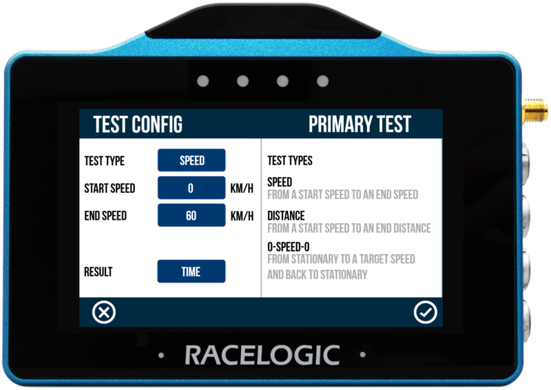
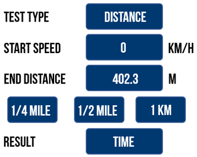
Test Type
Tap the blue Test Type button to choose between Speed, Distance or 0-Speed-0 (e.g. 0–100–0). The displayed parameters depend on the selected test.


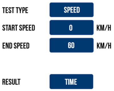

| Test Type | Parameters | ||
|---|---|---|---|
| Speed | Start Speed (km/h or mph) | End Speed (km/h or mph) | Result (time or distance) |
| Distance | Start Speed (km/h or mph) | End Distance (m or ft)* | Result (time or speed) |
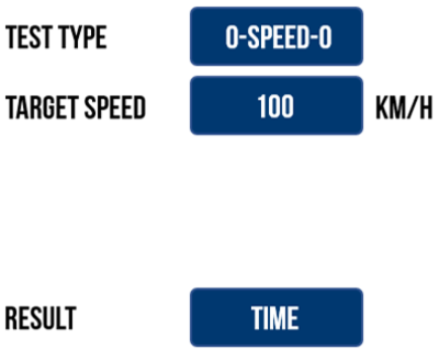
| 0-Speed-0 | Target Speed (km/h or mph) | Result (time or distance) | |
*Pre-set Distance buttons include 1/4 mile, 1/2 mile and 1 km.
Start/End Conditions
You can define the start and end conditions by pressing the corresponding buttons and using the keypad presented. If you are defining a Distance test, one of the pre-set distance buttons can be selected to quickly choose the test.
Save the new value by tapping the Confirm button in the bottom right corner of the screen, or return the Test Config screen without saving by tapping the Cancel button in the bottom left corner of the screen.
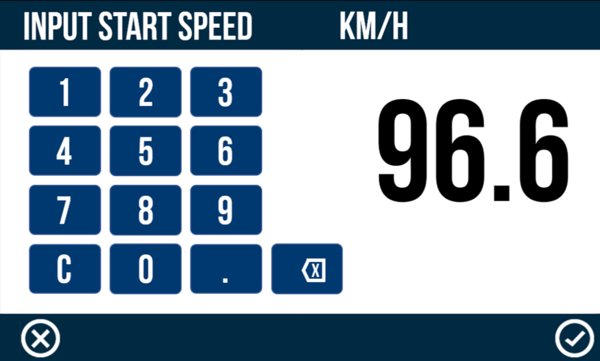
NOTES
- The maximum input value for speed is 999.9 and 9999 for distance.
- The minimum target value for a 0-Speed-0 test is 5 km/h/ 3.1 mph.
- Speed can be entered with up to 1 decimal place.
Result Type
The test result type for a selected test range can be changed by tapping on the current option.
Available result types include:
- Speed and 0-Speed-0 tests:
- Time (default) - Elapsed time between start and end conditions being met given as the selected range result.
- Distance - Distance travelled between start and end condition given as the selected range result.
- Distance tests:
- Time (default) - Elapsed time between start and end conditions being met given as the selected range result.
- Speed - Speed when end condition is met given as the selected range result.
Save or Discard a Test Configuration
Save the new test configuration by tapping the Confirm button in the bottom right corner of the screen, or return to the Accel Mode screen without saving by tapping the Cancel button in the bottom left corner of the screen.
The parameters of the primary test is displayed at the top right of the Primary Accel Screen. The Accel test ranges will be remembered for future use, even when using other display modes.
Accel Options
Alert at End/Target
By default, an audible and visual alert signals when either the test end criteria, or the target speed is met within a 0-Speed-0 test. The VBOX Touch will beep and the 4 LEDs across the top of the device will flash green for 0.5 s. Tap the button to disable.

By default, an audible and visual alert signals when either the test end criteria, or the target speed is met within a 0-Speed-0 test. The VBOX Touch will beep and the 4 LEDs across the top of the device will flash green for 0.5 s. Tap the button to disable.

NOTE
This setting will only apply to the Primary Test.
One-Foot Rollout
If enabled, all tests will not commence until 1 ft or 0.305 m distance has been covered.
When Enabled, '1ft' will appear next to the test header text on the Primary Accel screen and 'ONE FOOT ROLLOUT' will be displayed on the right-hand side of the new session header in the Test Results.

If enabled, all tests will not commence until 1 ft or 0.305 m distance has been covered.
When Enabled, '1ft' will appear next to the test header text on the Primary Accel screen and 'ONE FOOT ROLLOUT' will be displayed on the right-hand side of the new session header in the Test Results.

NOTE
Cannot be enabled if Slope Correct is Enabled.
Slope Correct
If enabled, VBOX Touch will apply a DB Scanner slope correction method to all speed to speed or speed to distance acceleration test results presented on the screen.
Slope correction only applies to the live display results in order to match DB Scanner third-party software post process corrections. It is not possible to apply post process corrections using Racelogic software programs.
If Enabled, 'DBSC' will appear next to the Test header text on the Primary Accel Screen and 'DBSCANNER SLOPE CORRECTED' will be displayed on the right hand side of the new session header within the Test Results.

NOTE
Cannot be enabled if One Foot Rollout is Enabled.
Decel
The Decel Settings is where you select the test parameters and manage other test options. You can change settings by tapping on the corresponding button next to an option.
Return to the Decel Mode screen, by tapping on the Exit button in the bottom left corner.
Decel tests can either be started from a specific speed or by using a VBOX Brake Pedal Trigger. Tap the blue Test Type button to toggle between the two options. Differing settings will be displayed depending on the selected test type.
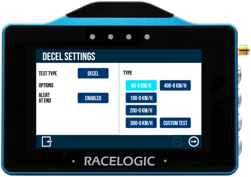
Decel Test
When the Test Type is set to Decel, you will see preset and custom test options on the right-hand side of the settings screen. The currently selected Decel test is highlighted on the screen and will be remembered for future use, even when you use other display modes.
Preset Tests
VBOX Touch is supplied with 5 preset speed decel tests. Tap a test to select it. The 60 – 0 KM/H test is selected by default.
- 60 – 0 (km/h or mph)
- 100 – 0 (km/h or mph)
- 200 – 0 (km/h or mph)
- 300 – 0 (km/h or mph)
- 400 – 0 (km/h or mph)
When a test is selected, the name will be displayed in the top right corner of the Decel Mode screen.
Custom Test
You can create a custom test where you choose your own start and end conditions by tapping the Custom Test button.
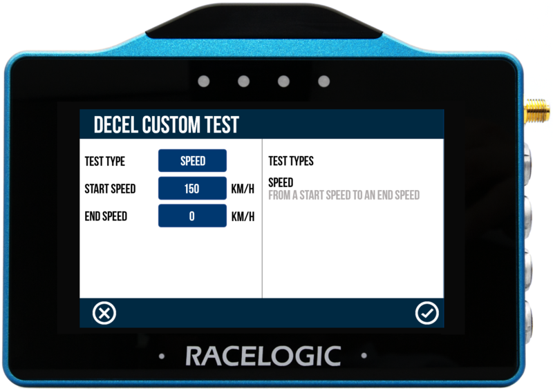
Define the start and end speed conditions by tapping the corresponding buttons and using the presented keypad to enter the speed values.
Save the new speed value by tapping the Confirm button in the bottom right corner of the screen, or return to the Decel Settings screen without saving by tapping the Cancel button in the bottom left corner of the screen.
NOTES
- The maximum input value for speed is 999.9 and can be entered up to 1 decimal place.
- The minimum start speed is 5 km/h/ 3.1 mph.
Save or Discard New Custom Test
Save the custom test by tapping the Confirm button in the bottom right corner of the screen, or return to the Decel Mode screen without saving it, by tapping the Cancel button in the bottom left corner of the screen.
When selected, the name of the new custom test is displayed in the top right corner of the Decel Mode screen. The last defined Custom Test will be remembered for future use, even when you select a preset test or another display mode.
Trigger Test
A Trigger test will start once VBOX Touch detects that the Minimum Trigger Speed is met and a VBOX Brake Pedal Trigger is activated. The test will stop when VBOX Touch detects that the vehicle is stationary (below 2.5 km/h).
When the test type is set to Trigger, The trigger settings become available on the right-hand side of the Decel Settings screen.
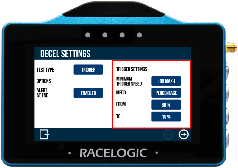
Minimum Trigger Speed
The minimum trigger speed is the speed at which trigger activation becomes valid. If the trigger is detected below this speed, the test will not start. Change this speed value by tapping the current value and using the presented keypad to enter a new value.

The minimum trigger speed is the speed at which trigger activation becomes valid. If the trigger is detected below this speed, the test will not start. Change this speed value by tapping the current value and using the presented keypad to enter a new value.

Save the new speed value by tapping the Confirm button in the bottom right corner of the screen, or return to the Decel Settings screen without saving by tapping the Cancel button in the bottom left corner of the screen.
MFDD Settings
Set the start and end period of the MFDD (Mean Fully Developed Deceleration) analysis period.
This deceleration figure is used to show the maximum deceleration figure a vehicle can achieve. It is usually the deceleration between 80% and 10% of the trigger activation speed, the time at which the vehicle is loaded up and braking at its highest achievable level.
The MFDD is calculated by the following formula (using default 80% – 10% value):
MFDD = ((v_08)² – (v_01)²) / (25.92 * (s_01 – s_08))
Where:
- v_08 is the speed at 80% of the brake trigger activation speed.
- v_01 is the speed at 10% of the brake trigger activation speed.
- s_01 is the distance at which the speed is v_01.
- s_08 is the distance at which the speed is v_08.
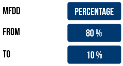
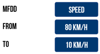
MFDD can be also calculated using Speed. Tap the blue MFDD button to toggle it to Speed.
Change a speed value by tapping the current value and use the presented keypad to enter the new value.
Save the new speed value by tapping the Confirm button in the bottom right corner of the screen, or return to the Decel Settings screen without saving by tapping the Cancel button in the bottom left corner of the screen.
Minimum/Maximum Values
From:
- Speed
- The maximum From speed selectable is the value inputted as Minimum Trigger Speed.
- The minimum From speed you can set is the greater value of 5 km/h or the To value +1.
- In general, the maximum input value for speed is 999.9 and can be entered with up to 1 decimal place.
- Percentage
- The maximum From percentage selectable is 100%.
- The minimum From percentage selectable is the To value +1.
To:
- Speed
- The maximum To speed selectable is the From value -1.
- The minimum To speed selectable is 0.
- Percentage
- The maximum To percentage selectable is the From value -1.
- The minimum To percentage selectable is 0.
Decel Options
Alert at End
By default, an audible and visual alert signals when the test end criteria is met. The VBOX Touch will beep and the 4 LEDs across the top of the device will flash green for 0.5 s. Tap the button to disable.
By default, an audible and visual alert signals when the test end criteria is met. The VBOX Touch will beep and the 4 LEDs across the top of the device will flash green for 0.5 s. Tap the button to disable.
Lap Timing
The Lap Timing Settings is where you select the test parameters and manage other test options. You can change settings by tapping on the corresponding button next to an option.
The Lap Timing Settings are split into two pages. Navigate between the pages with the Forward and Back arrows in the bottom right corner of the screen or by swiping the screen let or right.
Return to the Lap Timing Mode screen, by tapping on the Exit button in the bottom left corner.
Track
VBOX Touch has an inbuilt track database containing a vast number of circuits throughout the world.
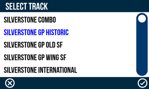
The unit will display the currently selected track based on the GPS location. If a location has multiple available track layouts, tap the Select button to see a list of the options. Choose a layout by tapping the desired option and then the Confirm button in the bottom right corner of the screen. Tap the Cancel button in the bottom left corner of the screen to return to the Lap Timing Settings screen without changing the track.
If you change the track layout, the LEDs will flash green twice and the unit will emit an audible confirmation notification. The layout will be remembered after each power cycle as long as it is determined to be local to the detected location.

VBOX Touch has an inbuilt track database containing a vast number of circuits throughout the world.
The unit will display the currently selected track based on the GPS location. If a location has multiple available track layouts, tap the Select button to see a list of the options. Choose a layout by tapping the desired option and then the Confirm button in the bottom right corner of the screen. Tap the Cancel button in the bottom left corner of the screen to return to the Lap Timing Settings screen without changing the track.
If you change the track layout, the LEDs will flash green twice and the unit will emit an audible confirmation notification. The layout will be remembered after each power cycle as long as it is determined to be local to the detected location.


NOTES
- If you press the Select button when you are not in the vicinity of a known track, the unit will display a NO LIST AVAILABLE message.
- When the selected track is changed, all existing lap timing values will be cleared and the new lap timing gates will be used.
Set Start/Finish Gate
Selecting the Set Start Gate option within the Lap Timing Settings manually set a start/finish line when moving, overwriting the line detected within the circuit layout. If you are defining a separate Finish Line, this gate will act as the Start Line only. More information about manually setting a start/finish line can be found above.

Selecting the Set Start Gate option within the Lap Timing Settings manually set a start/finish line when moving, overwriting the line detected within the circuit layout. If you are defining a separate Finish Line, this gate will act as the Start Line only. More information about manually setting a start/finish line can be found above.

NOTE
The vehicle must be moving >0.8 km/h and the unit have satellite lock to set a Start/Finish Line.
Set Finish Gate
Selecting the Set Finish Gate option within the Lap Timing Settings will manually set a Finish line when moving, overwriting the finish line detected within the circuit layout. A separate finish line must be set if you are using Standing Start Mode.

Selecting the Set Finish Gate option within the Lap Timing Settings will manually set a Finish line when moving, overwriting the finish line detected within the circuit layout. A separate finish line must be set if you are using Standing Start Mode.

NOTE
The vehicle must be moving >0.8 km/h and the unit have satellite lock to set a Finish Line.
Clear Finish Gate
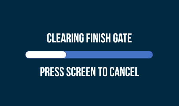
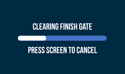
Selecting the Clear Finish Gate option within the Lap Timing Settings will clear the separate Finish line and will use the active Start line as a combined Start/Finish line.
A screen will be displayed, allowing you to cancel the finish line clear within 5 seconds by repressing the screen.
If the finish line is cleared, the LEDs will flash green twice and the unit will emit an audible confirmation notification.

NOTE
- When the finish gate is cleared, all existing lap timing values and lap history will be cleared.
- If finish line setting is cancelled, any live lap prediction for the current lap may be lost and unavailable for use.
Track Database
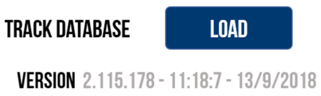
The Track Database installed within the VBOX Touch is updated whenever a new firmware file is uploaded on to the unit. However, you can also independently update the Track Database by pressing the Load Track Database button within the Lap Timing Settings. If an SD card is detected and a saved .tdb or .bdb track database file is located within the root directory of the SD card (not in the media or any other folder), the unit will start to load the file, which will update the tracks list but not overwrite any existing track information.
Progress of the track database update will be displayed via the LEDs; each lit LED will represent 25% of the process with all LEDs extinguishing when the process is complete.
This area also displays the currently installed track database version information.

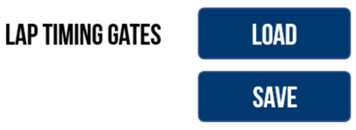
Lap Timing Gates
Load Start/Finish or Finish Line Gates
You can load previously saved or provided Start/Finish line gates by inserting an SD card with gate files contained within a SF LINES folder into the unit and then pressing the Load Lap Timing Gates button within the Lap Timing Settings. If only one file is located on the SD card, the file will be loaded immediately.
If multiple files are located on the SD card, the unit will display all available files. Select a file and tap the Confirm button in the bottom right corner of the screen to load it. Tap the Cancel button in the bottom left corner of the screen to return to the Lap Timing Settings screen without loading a gate file.
When loaded, a success screen will briefly display to show that it is was loaded successfully. If there are splits stored in the file, these will also be uploaded to the unit, up to a maximum of 10 gates/splits.

NOTE
When a new Start/Finish or Finish line gate is loaded, all existing lap timing values will be cleared and the new lap timing gates will be used.
Save Start/Finish Gates
To save the currently defined Start/Finish gates, tap the Save Lap Timing Gates button within the Lap Timing Settings. If an SD card is detected, it will be saved as a file named gates.spl within an SF LINES folder on the SD card. A save success screen will briefly display to show that it was saved successfully. If a gate file already exists on the SD card, VBOX Touch will display an overwrite cancel screen, which gives you 5 seconds to cancel the overwrite by tapping the screen.
Gate Width
Change the width of the Start/Finish gate by tapping the width value and using the presented keypad to enter the new width.
Save the new width by tapping the Confirm button in the bottom right corner of the screen. Tap the Cancel button in the bottom left of the screen to return to the Lap Timing Settings screen without saving the new gate width.
The default setting is 25 m/82 ft and is selectable from 3–100 m/10–330 ft. The value will be remembered after each power cycle.
This option is particularly useful if the VBOX Touch is not detecting the correct number of laps. When racing at a very narrow circuit where the pit lane is right next to the start line, it could be possible to trigger lap timing within the pit lane, giving an incorrect number of laps.

NOTE
The width can be entered with up to 1 decimal place.
Rolling Lap Time
This setting is enabled by default.
When Enabled, the Main Lap Timing Screen or Basic Lap Timing Screen will display the current live lap time. When a new lap starts, the previous lap time will be displayed for 5 seconds before reverting to displaying the current live lap time.
When Disabled, the previous lap time will be displayed.

Standing Start
When Standing Start is Enabled, VBOX Touch can use the position at the start of movement to trigger lap timing. This is particularly suitable for sprint style events as Lap Timing will only stop at a defined Finish Gate.
With standing start enabled, any existing Start/Finish or start gate will be ignored.
Once enabled, the LEDs will briefly flash green twice and the unit will emit an audible confirmation notification. Return to the Lap Timing Screen by pressing the Exit button in the bottom left corner.
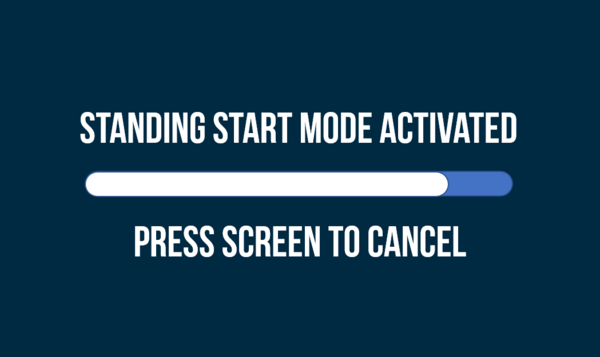
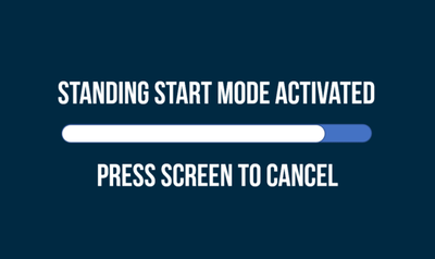
When the unit detects that the vehicle has been stationary (< 0.5 km/h) for 2 consecutive seconds, it will display an activation screen instructing you to wait 5 seconds before moving the vehicle. Tapping the screen, moving, or losing satellite lock before the standing start activation period has expired will cancel the feature.

When Standing Start is Enabled, VBOX Touch can use the position at the start of movement to trigger lap timing. This is particularly suitable for sprint style events as Lap Timing will only stop at a defined Finish Gate.
With standing start enabled, any existing Start/Finish or start gate will be ignored.
Once enabled, the LEDs will briefly flash green twice and the unit will emit an audible confirmation notification. Return to the Lap Timing Screen by pressing the Exit button in the bottom left corner.
When the unit detects that the vehicle has been stationary (< 0.5 km/h) for 2 consecutive seconds, it will display an activation screen instructing you to wait 5 seconds before moving the vehicle. Tapping the screen, moving, or losing satellite lock before the standing start activation period has expired will cancel the feature.

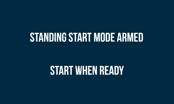
Once the activation period has expired, a 'Standing Start Mode Armed' screen will display, notifying you that the unit is ready for movement. Tap the screen to return to the Lap Timing Settings menu.
When VBOX Touch detects vehicle movement (> 0.5 km/h), it will assign the start gate at 90° to the detected heading. Lap Timing will only complete once the unit detects that a defined separate Finish Gate is crossed.

Delta-V Range
The brightness of the LED feedback in relation to the Delta-V speed can be adjusted. There are 3 options: 2 km/h/1.2 mph, 5 km/h/3.1 mph (default) and 10 km/h/6.2 mph. They relate to the maximum speed difference at which the LEDs are brightest. Tap the button to change the setting.

The brightness of the LED feedback in relation to the Delta-V speed can be adjusted. There are 3 options: 2 km/h/1.2 mph, 5 km/h/3.1 mph (default) and 10 km/h/6.2 mph. They relate to the maximum speed difference at which the LEDs are brightest. Tap the button to change the setting.

Using the default 5 km/h setting as an example:
Current lap is > 5 km/h quicker than the reference lap = LEDs are bright green
Current lap is 2.5 km/h quicker than the reference lap = LEDs are dull green
Current lap is the same speed as the reference lap = LEDs are off
Current lap is 2.5 km/h slower than the reference lap = LEDs are dull red
Current lap is > 5 km/h slower than the reference lap = LEDs are bright red
Reset Data
Selecting this option will reset the lap timing data, lap time history and reference lap. Once Reset is selected, a cancel timeout screen will display, allowing you to cancel the reset within 5 seconds by pressing the screen. After 5 seconds, the LEDs will briefly flash green twice and the unit will emit an audible confirmation notification.

Selecting this option will reset the lap timing data, lap time history and reference lap. Once Reset is selected, a cancel timeout screen will display, allowing you to cancel the reset within 5 seconds by pressing the screen. After 5 seconds, the LEDs will briefly flash green twice and the unit will emit an audible confirmation notification.

Fix Reference Lap
This option will fix the reference lap.
When fixed, the stored reference lap will not update if a faster lap is achieved. If there is no stored reference lap, the next complete lap will be used as the fixed reference lap.
Alternatively, you can fix the reference lap by triple-tapping on the Lap Timing Screen. When triple-tapping, you will see a cancel timeout screen, allowing you to cancel the reference lap fixing by tapping the screen within 5 seconds.
When a reference lap has been fixed, a padlock icon will show to the right of the reference lap on the Lap Timing Screen.
To unfix a reference lap, tap the Fix Reference Lap button to Disable it.
Alternatively, you can also unfix the reference lap by triple-tapping on the Lap Timing Screen. When triple-tapping, you will see a cancel timeout screen, allowing you to cancel the unfixing of the reference lap by tapping the screen within 5 seconds.

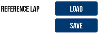
Reference Lap
Load a Reference Lap
You can load a previously saved or provided reference lap by pressing the Load button (as long as the unit is not logging and the vehicle is not moving). If an SD card is detected, the unit will display all .ref files located within the REF LAPS folder on the SD card. Select a file and then press the Confirm Button on the bottom right of the screen, or press the Cancel Button on the bottom left of the screen to return the Settings screen without saving
If confirmed, a load success screen will briefly display to show that it was loaded successfully.
If there are splits stored within the file, these will also be uploaded to the unit, up to a maximum of 10 gates/splits.
NOTE
When a new reference lap is loaded, the Start/Finish gate stored within the .ref lap will be applied as the active Lap timing gate if it is different to the currently loaded gate. If the gates are changed, all existing lap timing values will be cleared and the new lap timing gates will be used.
Save a Reference Lap
If a reference lap has been created, you can save the lap for future use (as long as the unit is not logging and the vehicle is not moving) by pressing the Save button. If an SD card is detected, it will be saved as a file named lap.ref within a REF LAPS folder on the SD card. A save success screen will briefly display to show that it was saved successfully. If a reference lap file already exists on the SD card, VBOX Touch will display an overwrite cancel screen, which gives you 5 seconds to cancel the overwrite by pressing the screen.
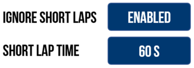
Ignore Short Laps
Make VBOX Touch ignore short laps when creating the reference lap. Enable this option and enter a minimum lap time that is acceptable for a reference lap.
Set the minimum lap time by tapping the Short Lap Time button and using the presented keypad to enter the new lap time.
Save the minimum lap time by tapping the Confirm button in the bottom right corner of the screen. Tap the Cancel button in the bottom left corner of the screen to return to the Lap Timing Settings screen without saving a minimum lap time.
The default setting is 60 seconds, but you can select a time between 10 and 86400 s. The unit will remember the value after each power cycle.

NOTE
Time can only be inputted as a whole number.
Ignore Double Distance Laps
This option is Disabled by default.
When Disabled, VBOX Touch will create a new reference lap, even if the lap distance is more than double the stored reference lap. This is useful if you are perhaps warming up on a smaller part of a longer circuit (for example the Nurburgring circuit and Nordschleife) and you want the reference lap to update once you have moved on to the longer circuit.
When Enabled, VBOX Touch will not update the reference lap when the lap distance is more than double the stored reference lap. This can, for example, be useful when the in-lap may cover more than double the distance of the reference lap.
Speed
The Speed Settings is where you select the test parameters and manage other test options. You can change settings by tapping on the corresponding button next to an option.
Return to the Speed Mode screen, by tapping on the Exit button in the bottom left corner.
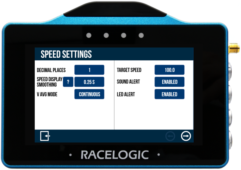
Decimal Places
Adjust the number of decimal places displayed for speed values across all Speed displays, between 0, 1 (default) and 2 decimal places.
Tap the button to cycle through the options.

Adjust the number of decimal places displayed for speed values across all Speed displays, between 0, 1 (default) and 2 decimal places.
Tap the button to cycle through the options.

Speed Display Smoothing
Apply smoothing to live speed values.
Available options include 0.0 s, 0.25 s (default), 0.5 s and 1.0 s and refer to the amount of time that the displayed data is averaged by.
Tap the button to change the smoothing level.

Apply smoothing to live speed values.
Available options include 0.0 s, 0.25 s (default), 0.5 s and 1.0 s and refer to the amount of time that the displayed data is averaged by.
Tap the button to change the smoothing level.

IMPORTANT
This option will smooth live speeds displayed in all relevant screen modes.
NOTES
- Smoothing only applies to the screen displays, not recorded data.
- It introduces a slight delay to the displayed value.
V Avg Mode
Select if the average speed on the Average Speed Screen is calculated as Continuous or Moving.
- Continuous: Average speed will start to calculate as soon as an SD card is inserted and initialised.
- Moving: Average speed will start to calculate as soon as a speed over 0.8 km/h is detected. calculations will stop when speed is less than 0.8 km/h.

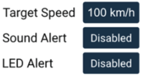
Target Speed
Define a Target Speed by tapping on the Target Speed button and using the presented keypad to enter the required speed (with up to 1 decimal place).
Save the target speed by tapping the Confirm button in the bottom right corner of the screen. Tap the Cancel button in the bottom left corner of the screen to return to the Speed Settings screen without saving the target speed. The value will be remembered after each power cycle.
The target speed will be displayed underneath the speed value on the Speed, VMAX and Average Speed screens.
VBOX Touch will alert you when you reach the target speed, using wither the LEDs, an audible beep, or both. When one or both of the alerts are enabled, VBOX Touch will apply the target speed.
- Audible alert = continuous 2-second beep
- Visual alert = all 4 LEDs will flash green
Alerts will only show once, unless the vehicle has been stationary since the previous alert.

General Settings
This menu contains units, logging mode, save format and brightness options.
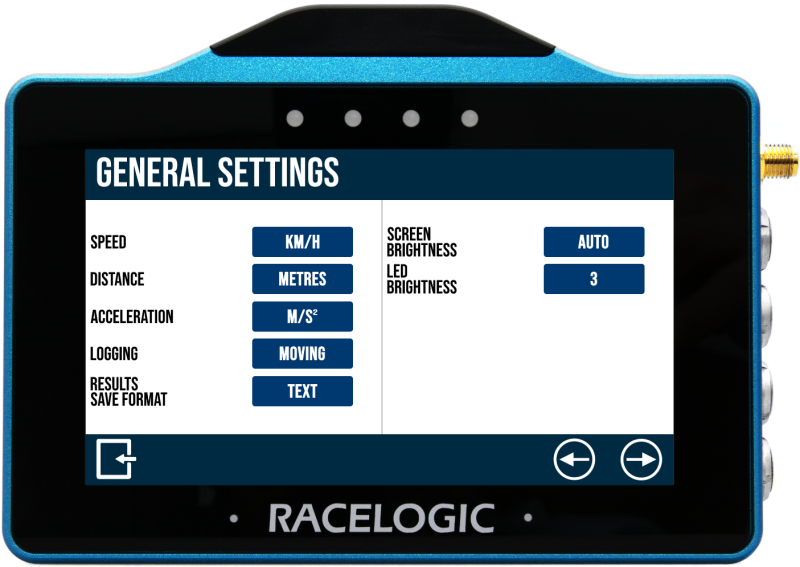
Speed
Change the speed units between km/h and mph.
Changing the speed units will affect all visual speed parameters on all screens, unit labels will change and all speed values will be automatically recalculated accordingly.
Tap the button to change the units.
Distance
Change the distance units between metres and feet.
Changing the distance units will affect all visual distance parameters on all screens, unit labels will change and all distance values and results will be automatically recalculated accordingly.
Tap the button to change the units.
Acceleration
Change the acceleration units between m/s² (default) and g.
Changing the acceleration units will affect all acceleration references on all screens, unit labels will change and all acceleration values and results will be automatically recalculated accordingly (with the exception of the PK G acceleration and deceleration test values).
Tap the button to change the units.
Logging
Toggle between 2 logging modes.
Tap the button to change the mode:
Continuous
VBOX Touch will start logging as soon as an SD card is inserted and initialised.
Moving (default)
VBOX Touch will start logging as soon as an SD card is inserted and it detects a speed of more than 0.5 km/h.
It will pause the logging when it detects a speed that is less than 0.5 km/h for 3 seconds, and will recommence once the speed is greater than 0.5 km/h again, appending the same file.
NOTES
- Manually pressing the SD Card Icon will manually start and stop recording, regardless of which logging mode is set.
- A new data file is created every time the VBOX Touch starts/stops logging, data is not appended to an existing data file.
- Continuous logging mode should be selected if you are using a Hand Held Start/Stop Logging Switch (RLVBACS010) to control logging.
Results Save Format
Change the data format of the results saved (to the inserted SD card) from the test history screens.
Choose between text format (.txt), the default option, and comma-separated values format (.csv).
Screen Brightness
Adjust the screen brightness between 5 levels, where 1 is the dimmest and 5 is the brightest.
An Auto setting is also available, which uses the internal ambient light sensor to adjust the screen brightness automatically. In dark conditions, the screen brightness will be dimmed, and in brighter conditions the screen will be brightened.
Tap the button to cycle through the available options.
LED Brightness
Adjust the LED brightness between 5 levels, where 1 is the dimmest and 5 is the brightest setting, or turn the LEDs off.
Tap the button to cycle through the available options, the LEDs will preview the brightness level.
CAUTION
LED Brightness level 5 is extremely bright!
Date & Time Settings
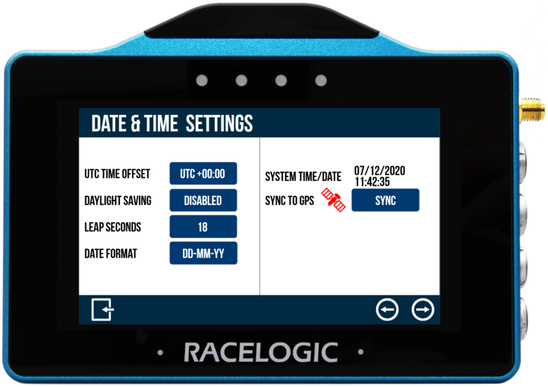
UTC Time Offset
The UTC offset value is set as '+00:00' by default.
Change it by tapping the UTC Time Offset button and use the Plus (+) and Minus (-) buttons to select the desired time zone offset values (including available 30 and 45 minute offsets).
Pressing and holding a button will fast-scroll through available valid time settings.
Minimum: -12:00; maximum: +14:00.
Save the new offset value by tapping the Confirm button in the bottom right corner of the screen. Tap the Cancel button in the bottom left corner of the screen to return to the Date & Time Settings screen without saving a new offset.
NOTE
The setting cannot be changed if the unit is moving or logging, if you try and change the setting a warning message will appear.
Daylight Saving
This option is Disabled by default.
When Enabled, this setting adds +1:00 hr to the local time setting.
NOTE
The setting cannot be changed if the unit is moving or logging, if you try and change the setting a warning message will appear.
Leap Seconds
The leap second value is set as '18 s' by default.
Changed it by tapping the Leap Seconds button and using the presented keypad to enter a new leap second value (maximum input value is 99).
Save the new leap second value by tapping the Confirm button in the bottom right corner of the screen. Tap the Cancel button in the bottom left corner of the screen to return to the Date & Time Settings screen without saving a new ;eap second value.
NOTE
The setting cannot be changed if the unit is moving or logging, if you try and change the setting a warning message will appear.
Date Format
Change the date format between DD-MM-YY (default) and MM-DD-YY.
System Time/Date
This displays the current time and date being used by the system.
They are displayed within the .vbo header file, file date created time stamp, the acceleration history results session header, deceleration history results session header, laps history filename and the gates file (.spl) header.
NOTE
The time/ date displayed by the unit may be inaccurate until a valid satellite lock is achieved. The unit will then update to the correct time/date as long as the unit is not logging.
Sync to GPS
This feature will synchronise the internal real-time clock (RTC) to GPS time as long as the unit has obtained GPS time (no GPS time is indicated by a red satellite icon), isn't moving and isn't logging.
Tap to start the synchronisation progress.
Serial Port Settings
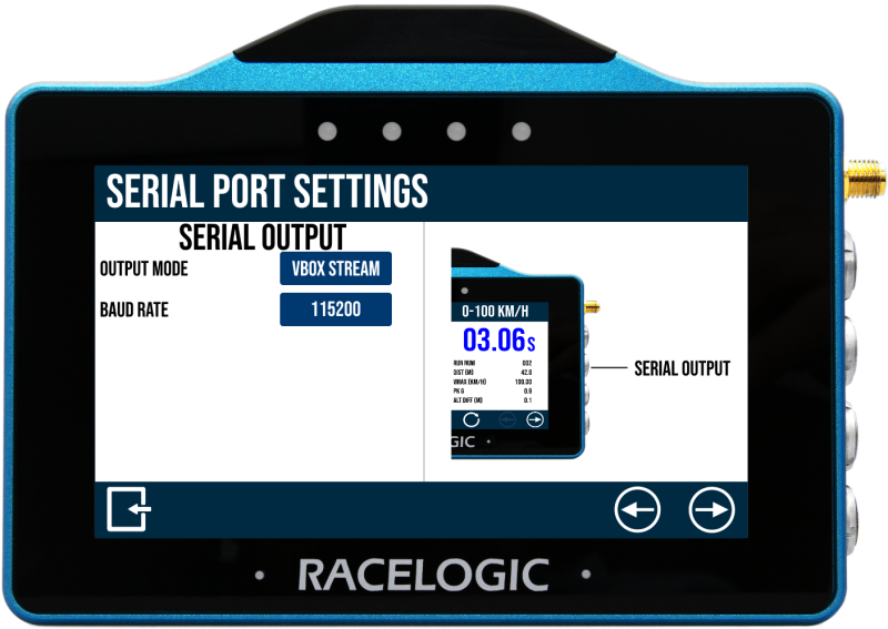
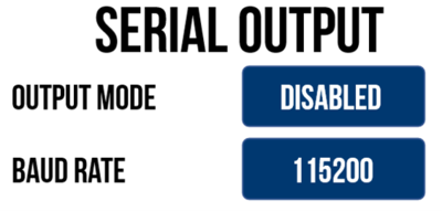
Serial Output
Serial output is available on the top CAN/Serial port of the VBOX Touch.
Output Mode
Choose the output mode of the serial port:
- VBOX Stream
- Lap Timing
- Disabled (default)
VBOX Stream allows you to connect VBOX Touch with a computer using an RLCAB001 and conduct online testing with VBOX Test Suite.
The Lap Timing option will output lap timing parameters.
Baud Rate
Displays the serial output baud rate, set as 115200 kbit/s.
Diagnostics
The Diagnostics menu is the final screen in the Settings menu.
It displays basic GNSS receiver and VBOX information.
The satellite icon at the top of the screen is the quickest way to determine if the unit has a valid satellite lock. When lock is acquired, it will display as solid green. When there is no satellite lock, the icon will flash red.
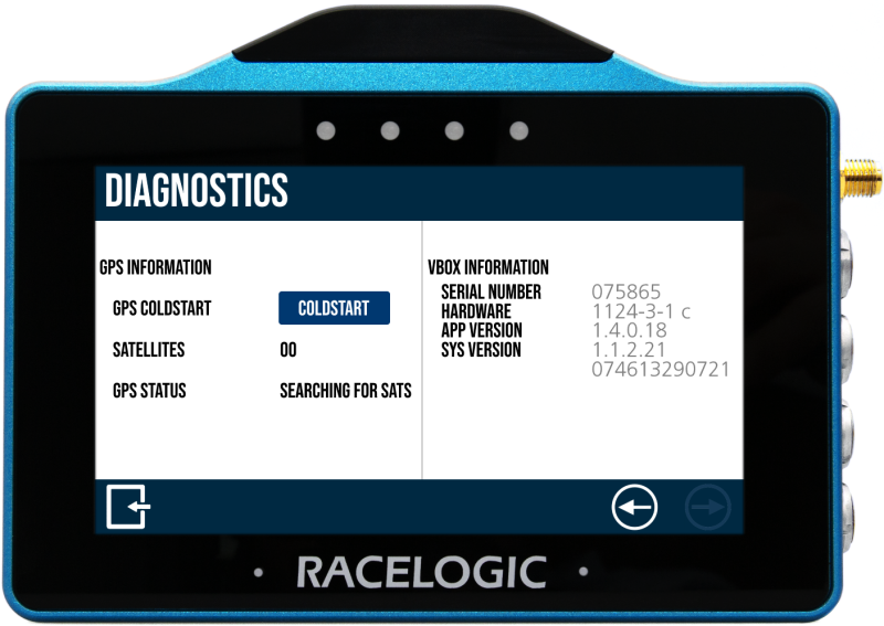
GPS Information
Coldstart
Tap the Coldstart button to perform a coldstart on VBOX Touch.
The receiver will clear any data currently stored in its internal memory. You may need to do this when the GPS engine has locked up or if VBOX Touch is struggling to acquire a satellite lock.
The unit will make an audible sound and a ‘PLEASE WAIT’ message will be displayed on the screen which will count down from 3. The number of satellites will then be displayed as '00' and GPS status will show ‘SEARCHING FOR SATELLITES’ until the satellite lock has been acquired. It will take approximately 25 to 30 seconds for the unit to reacquire the satellite lock.
Satellites
Displays how many satellites the receiver is currently using.
GPS Status
This indicates the current GPS lock status of the unit: When the unit is searching for a valid satellite lock, ‘SEARCHING FOR SATELLITES’ is displayed. When the GPS receiver has acquired a satellite lock, one of the following will be displayed:
- STANDALONE: Position computed from GNSS only.
- CODE DIFF: Position computed from assisted SBAS corrections.
VBOX Information
This section displays the device serial number, firmware version number and hardware version number. This information is useful in the event of troubleshooting a potential issue with the VBOX Touch unit.
- Support for external switch logging control.
- Brake Trigger test functionality.
- Acceleration Test Results will remain on the screen until it detects a speed of more than 5 km.
- 0-Speed-0 tests now sound the alert at target speed.
- Improved Result History list.
- The default speed smoothing value is now 0.25.
- End-of-test alert is enabled by default.
- Increased maximum satellites used to 12.
- Performance tests will reset when satellites drop.
- Add/clear a separate finish line.
- Standing-start lap timing mode.
- DB scanner slope correction mode for accel tests.
- Time and date settings.
- New logging icon (white) used when logging is primed and waiting for the Real-Time Clock to sync.
- Improved mode alerts.