| PIN | I/O | Function | Range |
|---|---|---|---|
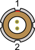
| 1 | I | Power+ | 8 - 30 V |
| 2 | I | Ground | 0 V |

| PIN | Name | Function | Range |
|---|---|---|---|
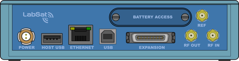
| Center | RF IN | RF Signal InputDC bias for active antenna | Bias output 2.8 - 3 V |
| RF OUT | RF Signal OutputDC Blocked | ||
| REF | 10 MHz Reference Clock Input | ||
| Chassis | - | Ground |
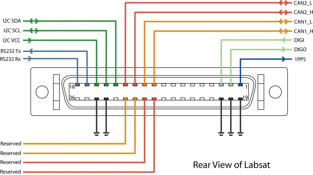
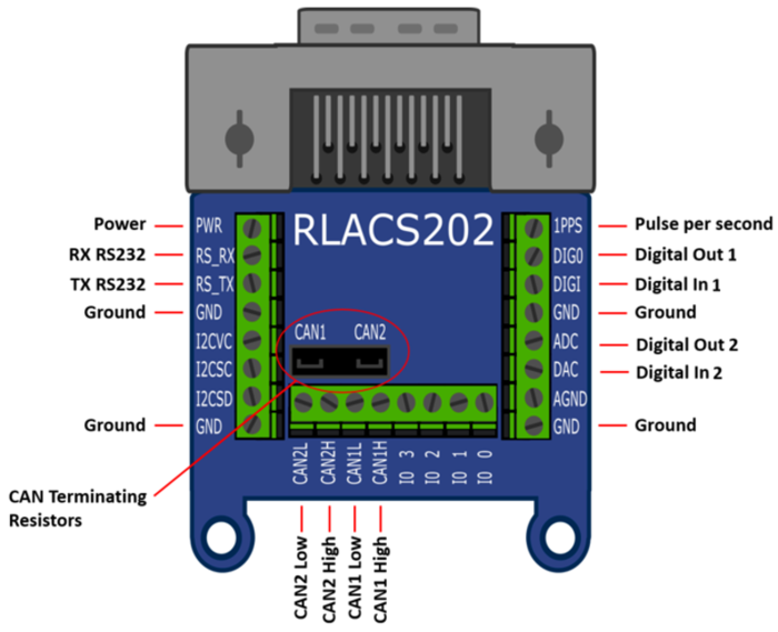
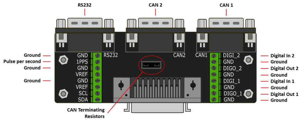
The 'EXPANSION' connector on the rear of LabSat 3 gives access to a number of signals including CAN Bus, RS232, 1PPS and Digital input/output. Accessory RLACS202 is used to provide user signal access for integration into the users test system.
| Number | Name | I/O | Function |
|---|---|---|---|
| 1 | 1PPS | O | Signal from Internal GNSS monitor. Becomes active when monitor is locked. 5 V Level. 25 mA |
| 2 | DIGO | O | User digital output. 5 V Level. 25 mA max |
| 3 | DIGI | I | User digital input. Up to 12 V input level. Detection threshold=2.5 V |
| 4 | - | - | - |
| 5 | - | - | - |
| 6 | - | - | - |
| 7 | - | - | - |
| 8 | - | - | - |
| 9 | - | - | - |
| 10 | CAN 1 H | I/O | CAN Bus High Channel 1 – Standard ISO 11898 voltage signal levels for CAN |
| 11 | CAN 1 L | I/O | CAN Bus Low Channel 1 – Standard ISO 11898 voltage signal levels for CAN |
| 12 | CAN 2 H | I/O | CAN Bus High Channel 2 – Standard ISO 11898 voltage signal levels for CAN |
| 13 | CAN 2 L | I/O | CAN Bus Low Channel 2 – Standard ISO 11898 voltage signal levels for CAN |
| 14 | I2C SDA | I/O | I2C Bus Data – Reserved for future use |
| 15 | I2C SCL | I/O | I2C Bus Data – Reserved for future use |
| 16 | I2C VCC | I/O | I2C Bus Data – Reserved for future use |
| 17 | RS232 Tx | O | RS232 data output. NMEA Data from GNSS monitor or User RS232 data if enabled. Standard RS232 Level |
| 18 | RS232 Rx | I | User RS232 data which is recorded if RS232 is enabled in Digital configuration menu. Standard RS232 Level |
| 19 | Ground | O | Ground Connection |
| 20 | Ground | O | Ground Connection |
| 21 | Ground | O | Ground Connection |
| 22 | - | - | - |
| 23 | - | - | - |
| 24 | - | - | - |
| 25 | - | - | - |
| 26 | - | - | - |
| 27 | - | - | - |
| 28 | IO_0 | I/O | Reserved |
| 29 | IO_1 | I/O | Reserved |
| 30 | IO_2 | I/O | Reserved |
| 31 | IO_3 | I/O | Reserved |
| 32 | - | - | - |
| 33 | Ground | O | Ground Connection |
| 34 | Ground | O | Ground Connection |
| 35 | Power | O | Connected to input power – Max 250 mA |
| 36 | Power | O | Connected to input power – Max 250 mA |
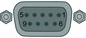
| PIN | I/O | Function | Range |
|---|---|---|---|
| 2 | O | Tx | RS232 data output. NMEA Data from GNSS monitor or User RS232 data if enabled. Standard RS232 Level |
| 3 | I | Rx | User RS232 data which is recorded if RS232 is enabled in Digital configuration menu. Standard RS232 Level |
| 5 | O | Ground | - |
| PIN | I/O | Function | Range |
|---|---|---|---|
| 2 | I/O | CAN Low | CAN Bus Low Channel 1/2 – Standard ISO 11898 voltage signal levels for CAN |
| 7 | I/O | CAN High | CAN Bus High Channel 1/2 – Standard ISO 11898 voltage signal levels for CAN |