06 - TC Setup Software
Download our TC Setup Software from here.
Installation
To install the traction control software, insert the CD into your CD-ROM drive. After a few seconds the “Install shield” prompt should appear. If the CD does not auto-run then browse the CD and double-click the 'SETUP' icon to start the install process. The install wizard will then guide you through the installation process.
Alternatively the software can be downloaded from our website, link above. Once downloaded decompress the folder using a utility such as 7 zip or Winzip then run the software from the uncompressed folder.
Connecting the traction control to the computer
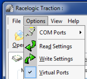
Connect a serial data cable from your computers COM port to the diagnostic lead of the traction control. Most modern laptops do not have a serial port, if this is case use a USB to RS232 Serial convertor and ensure virtual ports is ticked in the software.
Start the software and from the options menu select the COM port which you have connected to the traction control via the serial lead.
Apply power to the traction control.
Transferring settings from the traction control
The supplied software allows you to adjust the settings which are stored within the traction control. To discover what values are set inside your traction control, select ‘Read Settings’ from the options menu. The software will now communicate with the traction control. If all is successful, a green bar will temporarily appear at the bottom of the screen. All the values read from the unit will now be displayed in the software.
If the software failed to communicate with the traction control, a red bar will temporarily appear at the bottom of the screen. Please check that you have selected the correct COM port from the options menu, the traction control is powered up and the serial lead still connected from your computer to your traction control unit.
Note: It is a good idea to save the values read from your traction control using the ‘save as’ option in the file menu in case you need to reset these values.
Transferring settings to the traction control
Once you have changed the settings in the software, you must write these values into your traction control.
Select ‘Write Settings’ from the options menu. The software will now communicate with the traction control. If all is successful, a green bar will temporarily appear at the bottom of the screen. All the values are now written into the traction control unit.
If the software failed to communicate with the unit, a red bar will temporarily appear at the bottom of the screen. Please check that you have selected the correct COM port from the options menu, the traction control is powered up and the serial lead is connected from your computer to your traction control unit.
Software layout and options
Main Window
The software has a main menu bar with shortcut buttons shown below the menu. This menu is split into four sections as shown below.
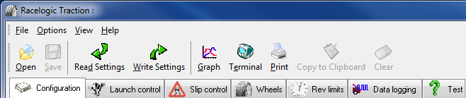
File Menu
'Open’ allows you to load a file into the software containing previously saved settings.
‘Save’ saves the current file.
‘Save As’ allows you to save all the current settings to a file of a different name.
‘Printer Setup’ allows you to alter the configuration of your printer.
‘Print’ allows you to make a printout of the Traction file settings.
‘Email’ allows you to directly send your settings to Racelogic
‘Import’ allows you to import ‘.tra’ settings files.
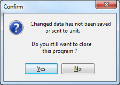
'Exit’ This will close the software. If you have made changes to any values and have not either saved the data to a file or sent the values to your traction control unit a warning message will be displayed prompting changes to be saved or discarded.
This is to prevent accidental closure of the software. If you are sure you want to close the software losing the modified data select ‘Yes’
.png?revision=1) |
.png?revision=1) |
Options Menu
Select COM port
|
Each time you move the cursor to the ‘Select COM port’ option, the software detects which COM ports are available on your computer. Note: If your COM port is higher than 6, then it may be necessary to first run the software as the system administrator in order to select the port. To do so open the folder where the Traction software is kept, right click on “Traction_MKII.exe” and select Run as administrator. |
|
|
|
|
|
Now all COM ports available on the laptop will be listed. |
|
|
Note that when using USB to RS232 Serial convertor Virtual Ports must be ticked (as above) in order to select the COM port, otherwise the port will remain greyed out. |
|
.png?revision=1)
.png?revision=1)
.png?revision=1)
.png?revision=1)
Read Settings
.png?revision=1)
When ‘Read Settings’ is selected, the software communicates with the traction control connected via the serial port lead and reads out all the traction control settings. These values are then displayed in the software.
Note: you cannot read from the unit whilst the ‘real time’ function is running.
Write Settings
.png?revision=1)
When ‘Write Settings’ is selected, all the settings shown in the software are written into the unit connected via the serial lead.
Note: you cannot read from the unit whilst the ‘real time’ function is running.
View menu
|
Selecting ‘Toolbars’ will give you the options of locking or freeing the toolbars. |
|
|
Selecting ‘Graph’ will open up the graph window. SEE USING GRAPH Selecting ‘Terminal’ will open up a window allowing direct communication with the traction control. SEE USING TERMINAL |
|
.png?revision=1)
.png?revision=1)
Using the graph
|
Clicking on the Graph icon will bring up a new window. This graphical display allows you to display wheel speeds, RPM and cut levels in real time, and to save and view the resultant graphs. |
.png?revision=1) |
.png?revision=1)
Help menu
Help will launch the manual automatically or allow you to find it yourself
.png?revision=1)
About
Selecting ‘About’ will open a window showing version number of this software.
.png?revision=1)
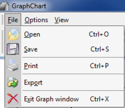
File menu
.png?revision=1)
Open
This allows you to load in data previously saved and show it on the graph.
Save
This allows you to save the data currently shown on the graph.
This allows you to print a copy of the graph.
Export
This allows you to export the graph data in the form of a picture ( i.e. Jpg, Bitmap, Gif) or as data to allow you to load it into some other software i.e. Microsoft Excel.
Instead of saving to a disk, you can send the data via email by selecting ‘Send’.
Exit Graph window
This will close the graph window and return you to the main window.
Options menu
.png?revision=1)
Axis
This option allows you to alter axis setting on the graph such as maximum figures and colours.
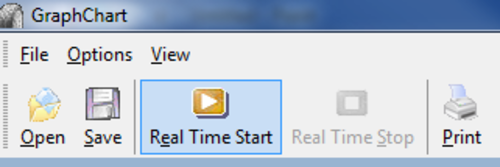
Real Time Start
Begin a real time session. When selected you will be asked if you would like to save the data in this session (recommended to allow the user to reference the data at a later point)
|
|
|
.png?revision=1)
.png?revision=1)
Real Time Stop
Select to end the real time session.
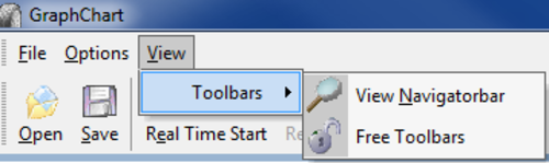
View Menu
The View menu enables the freeing of the toolbars in order to create more screen space.
.png?revision=1)
Graph Functions
Zoom
You can zoom into the graph to show an area in more detail.
To zoom, first place the mouse pointer at position ‘A’ then holding down the left mouse button drag the mouse down to point ‘B’. Then release the mouse button.
.png?revision=1)
The graph window will now show a zoomed view of the area selected with the mouse.
.png?revision=1)
To un-zoom click and drag the mouse on any portion of the graph screen in the opposite direction (left to right). The full graph will then be redisplayed.
Pan
You can move the whole graph by holding the right mouse button and dragging the mouse around.
Cursor
When ‘Real time’ is stopped, the full graph is shown in the window. A solid vertical line will also appear on the screen, this is the cursor. Wherever this is on the graph, the value of each trace it crosses will be shown at the bottom of the screen.
If you click on the graph using the left mouse button, the cursor will jump to that point.
You can select the cursor with the mouse and drag the cursor across the graph.
Instead of using the mouse to move the cursor, you can use the left and right arrow keys on your keyboard. Holding down the shift key as well, will move the cursor in larger steps.
Show / Hide data
|
You can temporarily remove data from the graph by clicking on its title eg ‘Front left (FL)’ at the bottom of the screen. This will bring up the following window: From here it is possible to alter the colour in which each wheel speed trace is displayed, and also to remove individual traces from the main graph display. |
|
.png?revision=1)
Traction Control Settings
To access the parameters stored in the traction control, select “Read Settings” from the options menu. The settings will then be displayed in the software. Whenever you make changes you will need to click on “Write Settings” to download to the unit.
Settings file can be saved via File – Save As. We would recommend you always save settings before making any changes.
Configuration Settings
.png?revision=1)
Maximum difference in wheel speeds
Maximum operating speed should be set to allow unfeasible differences in wheel speeds to be rejected. Program this value to ignore differences that could not possibly be generated by driving the wheels. E.g. – If in a launch condition the maximum wheel spin generated is 50 Km/h, program the maximum difference to 70 Km/h, any spikes or glitches over this value will then be rejected.
Default value: 655.35 kmh
Maximum Operating Speed
If your wheel speed signals generate electronic noise over a certain velocity, use this parameter to stop unwanted injector cuts. For example, wheel spin over 160kmh is very rare, so if you are experiencing cuts at this speed it may be necessary to introduce a figure in order to eradicate them.
Minimum Operating Thresholds:
Speed
This should be set to the minimum speed below which the sensors do not pick up any movement. This can be discovered by using the real time function of the software. Slowly pull away and monitor the wheel speeds in the real-time graph screen and wait for all four wheel speeds to register. e.g. – If all the wheel speeds are picking up correctly above 14 Km/h, program the Speed to 14.0 Kmh.
Default value: 14 kmh
Revolutions
The traction control system can be programmed not to operate below a certain engine Rpm. This is to stop the engine becoming 'bogged down'. If the car has a high revving 'cammy' engine, set this to the point at which the engine just starts to come on power.
Default value: 2000 RPM
Dry , Wet
This is set to allow a small difference in wheel speeds to enable turning sharp corners at low speeds. The system compares right front with right rear and left front with left rear. Adjust this value if the system cuts going round sharp corners when no wheel spin is occurring. Two values can be entered (WET and DRY) and can be switched using the manual adjuster to select wet or dry settings.
e.g. – Use the ‘Real Time’ function of the software to log data. Drive the vehicle and turn a sharp corner. Save the data from the graph window and examine the file. Look at the maximum difference between the wheel speeds (left front and left rear or right front and right rear) and enter this value.
Default value: Dry 4.5 kmh, Wet 3.5 kmh
Turning:
Minimum turning speed
The system constantly compares wheel speed values. If it detects a difference in front wheel speeds greater than the turning speed for a preset period of time (Time before turning is true) it assumes the vehicle is cornering and disregards the value set in Straight Line Override.
Default value: 0.45 kmh
Time before turning is true
The period of time the wheel speeds must exceed the turning threshold before the system assumes the vehicle is cornering.
Default value: 0.2 Seconds
Straight-line override
The system has software that calculates when the car is cornering and when the car is travelling in a straight line. Generally more traction control needs to be applied when the car is cornering. This value adds a percentage to each of the percentage slips when the traction control knows the car is travelling in a straight line. E.g. – If the straight-line override is set to 5%, this value will be added to each of the percentage slip values when the car is travelling in a straight line.
Default value: 5 %
Cylinders
The traction control system must be configured to the correct number of cylinders of the engine. e.g. For a 4 cylinder engine a value of 4 must be entered. If the incorrect Rpm is displayed under diagnostics, then change this value until the right Rpm is shown.
Default value: 4
Smoothing
Can be set from 0 - 5, level is normally set at 0 and should be increased depending upon the severity of the glitching. Level 5 should only be used for data logging. Please not that altering this value above 0 will adversely affect the speed of operation of the Traction system.
Default value: 0
Misfire mode
The traction control has two modes of engine misfire that define how the data in the cut tables is used.
.jpg?revision=1)
In non-sequential mode
With the 'Non sequential mode' enabled each level of cut will cause the traction control to cut a pre-determined factory set number of injectors. Different numbers of injectors are cut depending upon the severity of the misfire applied. The specific of how the injectors are cut over a period of time is defined by the data in the corresponding cut tables.
‘Sequence 1’ will control injector 1.
‘Sequence 2’ will control injectors 1 and 2.
‘Sequence 3’ and ‘Soft Cut’ will control injectors 1,2 and 4 (and 6 where applicable).
‘Hard Cut’ and ‘integral Cut’ will control all injectors.
In sequential mode
With the 'Non sequential mode' turned off, the next firing injector will be controlled by the cut sequence.
e.g. (using above Sequence 1)
| Injector 1 | Injector 2 | Injector 3 | Injector 4 | |
 |
Miss | |||
 |
Fire | |||
|
Miss | |||
|
Fire | |||
|
Fire | |||
|
Miss | |||
|
Miss | |||
|
Miss | |||
|
Fire | |||
|
Miss |
Suggested Cut Table settings when using sequential mode.
Slip control (applied to normal operation)
.png?revision=1)
Rev Limits (applicable to launch control and full throttle shift)
.png?revision=1)
With this method the severity of the misfire is directly associated with the data in the cut table.
To ensure the system does not create a double cut as slip levels are reduced, always begin each slip control cut table with a .jpg?revision=1)
Launch Control
.png?revision=1)
Common Settings
Slip override for slow speed getaway
An override percentage that is added to the overall percentage slip values during launch mode. e.g. If Slow Override speed threshold is set to 3.5Kmh and the percentage slip override for slow speed getaway is set to 15%, then below 3.5 Kmh 15% is added to each of the slip values.
Default value: 15 %
Delay slip override
Delay Slip Override, used in conjunction with the start delay. The value adds a percentage override to the slip parameters for a set period of time programmed as the Start Delay.
Default value: 0 %
i.e. if ‘Delay slip override’ is set to 5% and ‘Start delay’ is set to 2 seconds, 5% will be added to each of the percentage slip values for 2 seconds during launch mode.
Slip to reinstate traction control
|
The slip threshold under which the traction control will switch from Launch mode back to normal Traction Control operation. |
|
.png?revision=1)
DRY Settings, WET Settings
Hard Cut
Set the hard cut slightly above the soft cut to achieve a smooth rev-limit.
E.g. If the soft cut is at 4500 Rpm, set the hard cut at 4750 Rpm.
Two values can be entered under WET and DRY and can be switched using the manual adjuster to select wet or dry settings.
Default value: Dry 4800 RPM , Wet 4300 RPM
Soft Cut
Set the soft cut rev-limit to just below the desired Rpm. Two values can be entered under WET and DRY and can be switched using the manual adjuster to select wet or dry settings.
Default value: Dry 4500 RPM , Wet 4000 RPM
Start delay
The period of time at which the ‘Delay slip override’ percentage is added to the overall percentage slip values during launch.
Default value: Dry 2 seconds , Wet 2 seconds
Slow override speed threshold
This threshold works in conjunction with the ‘Slip Override For Slow Speed Getaway’. Below this speed the Percentage Override setting is added to each of the percentage slip values.
Default value: Dry 30 kmh , Wet 25 kmh
Slip Control
.png?revision=1)
The severity of the misfires can be changed by modifying any of the cut tables.
Sequence 1,2 & 3
Placing a will allow an injector to fire, putting a .jpg?revision=1) will prevent the injector from firing.
will prevent the injector from firing.
To quickly set all to either fire or non-fire, use the appropriate button in the ‘Set all to’.
Assert at
When a manual adjuster is fitted, the level set i.e. 5% is known as the ‘set allowable level’. Assert at is the value at which the cut table is used above the ‘set allowable level’.
e.g. Manual adjuster set to 10%
Sequence 1 ‘assert at’ is set to 5%
The traction control will allow the wheels to have a maximum 15% of slip. Then at this point (Manual adjuster + assert at) the traction control will start to reduce power using cut sequence 1 until it returns to a maximum of 15% slip.
To reduce power the traction control uses four levels of progressively intrusive cut. These are sequence 1,2,3 and Integral.
If the traction control is reducing power using sequence 1 and the slip reaches the value set for sequence 2, then the traction control will start to use sequence 2 instead of sequence 1.
Note: These same cuts are used for both wet and dry settings.
Default value: Sequence1: 5%, Sequence2: 10%, Sequence3: 15%
Integral settings
Placing a will allow an injector to fire, putting a will prevent the injector from firing.
Start After
If the wheels continue to slip despite the activation of sequence 3 cut then after a period of time defined by the ‘Start after’ value the integral cut is applied.
Default value: 0.4 Seconds
Wheels
.png?revision=1)
Driven / Reference
Wheel Diameter
The wheel diameters must be entered in millimetres, and must be the diameter of the tyre. This allows the system to calculate the rolling circumference.
Press the .jpg?revision=1) button and a window will appear.
button and a window will appear.
|
This lets you input the values as shown on the side of your tyre. |
.png?revision=1) |
|
E.g. 205 / 45 R 16 Default value: 550mm |
.jpg?revision=1) |
Pulses per revolution
The number of reference pulses per revolution must be entered for the reference and driven wheels of the car, this value corresponds to the number of slots, holes or teeth per revolution in each of the sensor discs.
Default value: 40
NOTE: After writing changes to the PPR the Traction must be turned off and on for the changes to take effect.
Wheel Assignment (FL ,FR ,RL ,RR )
|
Assign the correct channel to the correct side of the car. Check using the real-time graph function and spinning each wheel individually. |
.png?revision=1) |
Rev limits
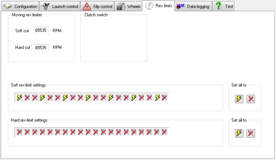.png?revision=1)
Moving rev limiter
Soft cut / Hard cut
Similar to the rev limits used for the Launch Control Function except these are operated whilst the car is moving. Again, the soft cut is operated at, say 5500 RPM and the hard cut is operated at a higher engine speed, say 5750 RPM.
These rev limits are used for the Power Shift function. It is activated by the clutch switch, and allows full throttle gearshifts to be carried out whilst the engine is prevented from over-revving.
Default value: Soft cut 65535 RPM , Hard cut 65535 RPM.
Note: a value of 65535 will set this function to OFF.
Clutch switch
The polarity of the clutch switch is normally open, which is then closed when the clutch pedal is depressed. If a normally closed switch is used, i.e. one that breaks connection when the clutch is depressed, tick the box.
Default value: enabled
Soft / Hard rev-limit settings
Placing a will allow an injector or spark to fire, putting a will prevent the injector or spark from firing.
To quickly set all to either fire or non-fire use the appropriate icon in the ‘Set all to’.
Data Logging (Only for TC8 units with battery backup memory)
.png?revision=1)
About
The Data Logging feature allows you to record all wheel speeds RPM and traction control activity over the period of time the traction control was active. The system will retain all information even if the box is switched off, but once the system has been switched off, the next lot of data will gradually overwrite the previous, so only the most recent run is recorded.
Enable Data Logging
Switch-able function, that allows data logging to be used.
Note: Data logging must be turned off for the diagnostic functions to work.
Default value: off
Sample Rate
The sample rate is a compromise between the resolution of the results versus the length of time available for logging. That means you could select ‘122Hz’ for the sample rate, which will give around 122 samples every second, but will only allow three minutes of sampling. It is best to use a quicker sample rate when data-logging standing starts, and a slower one when logging over the period of a race.
Default value: 122 Hz
| Sample Rate (Hz) | Total log time |
|---|---|
| 122 | 2 Minutes 58 Seconds |
| 81 | 4 Minutes 28 Seconds |
| 61 | 5 Minutes 57 Seconds |
| 49 | 7 Minutes 27 Seconds |
| 41 | 8 Minutes 56 Seconds |
| 35 | 10 Minutes 26 Seconds |
| 22 | 16 Minutes 24 Seconds |
| 15 | 23 Minutes 51 Seconds |
| 12 | 31 Minutes 19 Seconds |
| 9 | 38 Minutes 46 Seconds |
| 8 | 46 Minutes 13 Seconds |
| 7 | 53 Minutes 41 Seconds |
| 6 | 61 Minutes 8 Seconds |
| 5 | 68 Minutes 36 Seconds |
Clear Ram
Click on this button to clear the ram of any previous data. Alternatively the clear ram switch can be pressed when the system is powered up.
Upload
Click on this button to upload the data from the unit. The data will be visible in the graph window.
Test Injector cuts
This allows you to apply one of the cut sequences from the traction control to the engine. The cut will last for the length of time set in ‘Misfire for’.
Note: You cannot send a test command whilst the ‘real time’ function is running.
.png?revision=1)