05 - VBOX Video CAN Settings - Windows

VBOX Video HD2 has the ability to capture up to 80 CAN channels from Racelogic modules and/or from a vehicle CAN bus system.
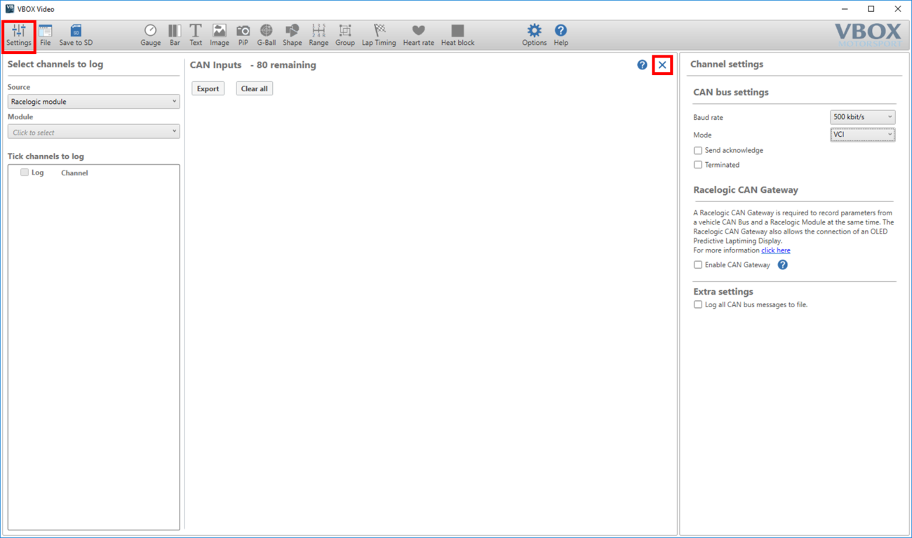
The CAN settings area can be accessed using the ‘Settings’ button in the top left menu bar.
.png?revision=1)
To return to the scene designer, either use the ‘Settings’ button again, or press the ‘X’ in the top right corner of the general settings area.
Overview
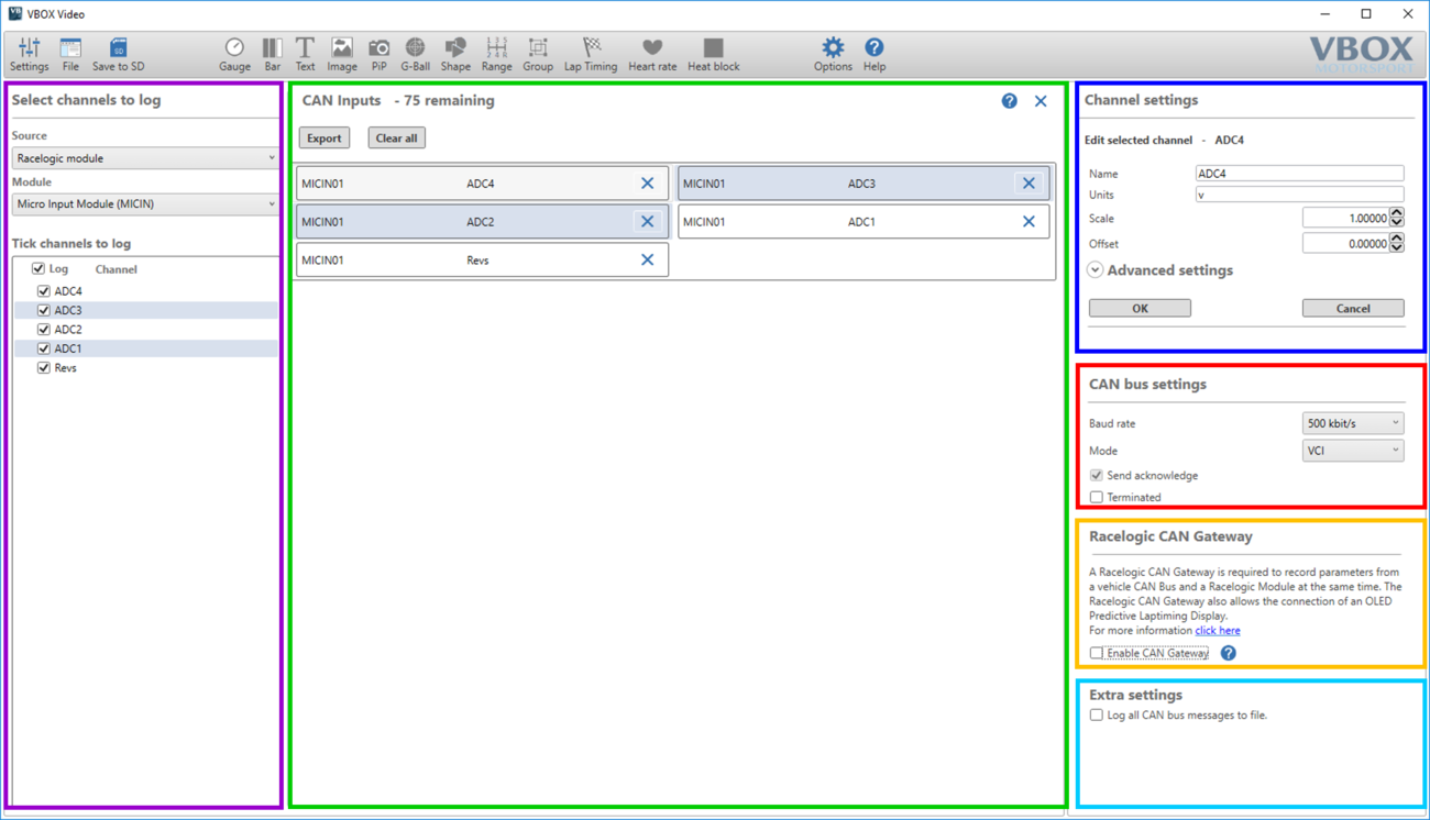
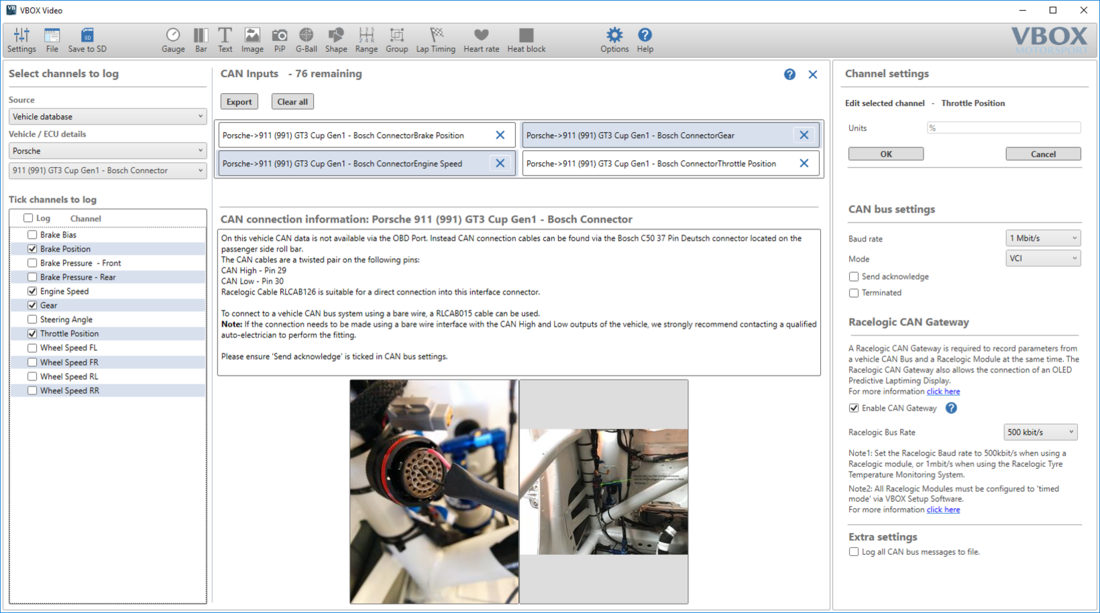
The six main areas of the CAN settings page are highlighted below.
Select channels to log
The purple box highlights the area where either a vehicle can be selected from the vehicle database within the software, a Racelogic module database can be selected, a CAN database file for a specific vehicle can be loaded, or a new CAN channel can be manually defined.
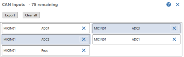
CAN Inputs
The green box highlights the areas which display all CAN channels that are currently set to log. A counter at the top of this window shows the number of remaining channel spaces. Clicking on a channel set to log will cause its settings to display in the channel settings area. Channels can be exported from this section into their own database using the top ‘export’ button.
Channel settings
The blue box highlights the settings for either the currently selected channel in the CAN Inputs section or the last selected channel in the Select channels to log section.
Expand the Advanced settings area to see all CAN channel settings.
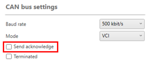
CAN bus settings
The red box highlights the settings for the HD2 CAN bus. See the CAN settings below for more information.
Notes:
- The Baud rate must match that of the connected unit/vehicle (Racelogic modules default is 500 kbit/s).
- Send Acknowledge is needed to allow communications with Racelogic Modules, but should not be used when connecting to most Vehicle CAN Bus systems.
Racelogic CAN Gateway
A CAN Gateway is required to record parameters from a vehicle CAN Bus and a Racelogic module at the same time. It also allows the connection of an OLED Predictive Laptiming Display. If you are using a CAN Gateway, select Enable CAN Gateway and then set the desired Racelogic Bus Rate from the drop-down menu.
When the configured scene is saved, a configuration file will need to be uploaded to the CAN Gateway. More information on connecting to a CAN Gateway can be found here.
Notes:
- The baud rate should be set to 500 kbit/s when using a Racelogic module, or 1 Mbit/s when using the Racelogic Tyre Temperature Monitoring System.
- All Racelogic modules must be configured to 'Timed mode' via VBOX Setup software, more information can be found here.
Extra settings
Enabling 'Log all CAN bus messages to file' will enable vehicle CAN bus data to be logged to a file for diagnostic purposes.
This setting should only be used for diagnostic purposes as it may affect the performance of your HD2 unit.
Note: Selecting this option will cause message delays/duplicates in the .vbo data.
CAN Bus Settings
Baud rate
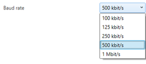
The default Baud rate of the HD2 is 500 kbit/s, which is correct for most light vehicles, and for when you log Racelogic Module data (assuming default module settings).
If this needs to be changed, the user has the option of selecting 100, 125, 250 or 500 kbit/s, or 1 Mbit/s.
Click here for details on how to physically measure the CAN Baud rate.
Mode
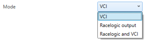
- VCI mode (default) should be used for vehicle CAN bus connection, or if data is being captured from Racelogic Modules.
- Racelogic Output mode should only be selected if the HD2 is to be connected to a CAN logging device. When selected, the HD2 will transmit GPS channel data onto the CAN bus in this format.
- Racelogic and VCI mode allows for the combination of the vehicle CAN bus or Racelogic Module data to be captured along with transmitting data to a CAN logging device.
Send Acknowledge
Racelogic modules and other CAN data loggers and sensors require an acknowledge pulse to be sent. However, it is not recommended to send these messages when connected to a vehicle’s CAN bus.
Click here for more information on CAN send acknowledge.
When logging data from a Racelogic Module, send acknowledge will be automatically turned on. Whenever this message is enabled, a warning message will appear telling the user that this could place unwanted data onto a connected vehicle CAN bus.
.png?revision=1)
Termination
When connecting to Racelogic modules and other CAN data loggers and sensors, additional CAN termination may be needed, depending on the specific setup. Click here for more information on CAN termination.
Logging CAN data from a Racelogic Module
Racelogic CAN modules have built-in CAN database files, which can be accessed within the left-hand panel of the CAN settings area.
To log data from a Racelogic module, select ‘Racelogic module’ from the ‘source’ drop-down list. The user can then select the desired module from the ‘Module’ drop-down list - shown below.
.png?revision=1)
When the desired module is selected, the channels available to log will be shown. To log all channels, tick the ‘log’ box at the top of the list. Channels can also be ticked to log individually.
.png?revision=1)
Once channels are ticked to log, they will appear in the centre ‘CAN Inputs’ list. At this point, they can be assigned to elements within the scene.
As soon as a Racelogic Module channel is ticked to log, this will also automatically enable CAN send acknowledge.
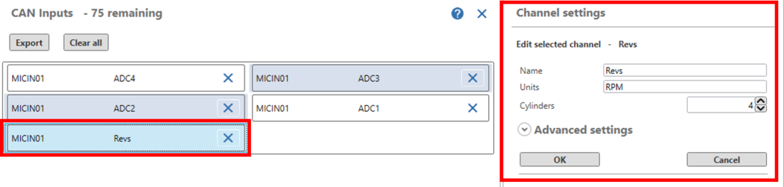
To edit the setup of any individual channel that is set to log, click on the channel of interest within the centre ‘CAN Inputs’ list. The channel settings will appear in the right-hand panel.
Micro / Mini Input Modules
Micro Input Module units have no user configurable settings, and are set up to work as standard with the HD2.
Note: all scenes included the scene library that are configured to log CAN, are set up to work instantly with the Micro Input Module.
Mini Input Module units, if purchased with the HD2, should be set up and ready to use. However, the Mini Input Module does have user configurable settings - click here for notes on how the unit should be set up.
Other Racelogic Modules
Compatible Modules: Inertial Measurement Units (IMU / YAW), 8 Channel Thermocouple (TC8), 8 Channel Analogue (ADC), Frequency Input Module (FIM).
Note: In order to communicate with VBOX Video HD2, Racelogic modules must be set into Timed CAN mode. For more information on how to do this, please see the user guide for the module in use.
Within the 'Mode Settings' section, ensure that 'VCI' is selected, and the 'Send Acknowledge' box is ticked.
Basic channel settings
When a Racelogic Module channel is selected, the user can easily edit the channel name, units, scale and offset within this area.
Click here for more information on scale and offset.
Note that when setting up the Revs input on a Micro Input Module, scale and offset are replaced with ‘Cylinders’ – simply enter here the number of cylinders in the vehicle engine and the scale and offset will be calculated automatically.
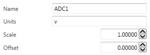
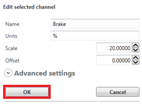
The example below shows the setup for an analogue sensor picking up 0 - 5 V to display as 0 - 100 % brake data.
|
Default settings |
Settings changed to show Brake % |
.png?revision=1)
.png?revision=1)
When any changes have been made to a CAN channel, click OK to save these changes.
.png?revision=1)
Advanced channel settings
This should only be used if the module in use has had its setup changed from the default settings. Likewise, any settings changed here must be reflected in the Racelogic module – this can be done within VBOX Setup software.
For more details, please check the correct Racelogic Module manual.
Logging Vehicle CAN bus data
In order to capture data from a vehicle CAN bus system, the HD2 system must have:
- The correct vehicle specific CAN database loaded into the scene file.
- A successful hardware connection into the vehicle's CAN bus.
Software setup for vehicle CAN logging
The Racelogic vehicle CAN database contains hundreds of different signals, for many different makes and models of vehicles. VBOX Video Setup software enables you to search the vehicle database and select required channels through the software. Alternatively, you can upload a CAN database file (.REF, .DBC, .VCI) for your vehicle from external sources.
Vehicle database
This option enables you to browse the Racelogic Vehicle CAN database within the software and select your vehicle.
Within the CAN Settings area of VBOX Video Setup software, Select ‘Vehicle database’ under the ‘Source’ drop down list. You can then select the desired vehicle from the ‘Vehicle / ECU details’ drop down lists (as shown below).
.png?revision=1)
Once selected, CAN channels specific to your vehicle will appear under the 'Tick channels to log' section. If available, CAN connection information for the vehicle will also appear within the centre window. Selecting an image will open a web browser page displaying the enlarged image.
Load database
This option enables you to upload a CAN database file (.REF, .DBC, .VCI) that has been custom created for you by Racelogic or that you have received from external sources.
Within the CAN Settings area of VBOX Video Setup software, Select ‘User configurable’ under the ‘Source’ drop down list. This will cause a button to appear labelled ‘Load database’. Select this button to load the CAN database file.
.png?revision=1)
Select the CAN database file (.REF, .DBC, .VCI), the channels will then appear for selection.
Logging channels
Tick the channels to log, either by individual section, or tick the ‘Log’ box at the top to log all channels within the database file (maximum of 80).
.png?revision=1)
Once channels are ticked to log, they will appear in the ‘CAN Inputs’ List. At this point they can be assigned to elements within the scene.
.png?revision=1)
Clicking on a channel set to log will cause the settings to display in the ‘Channel settings’ area.
If using a .REF file (Racelogic encrypted file), then this data is encrypted, so no settings will show.
.png?revision=1)
Connecting HD2 to the Vehicle CAN Bus
After the software configuration is complete, a hardware connection must be made to the vehicle’s CAN bus system.
This can be done into some vehicles' OBDII (On-Board Diagnostics) port, or directly into the CAN bus wires using a bare wire connection, depending on the vehicle make/model.
Racelogic provides details of vehicle connection points including images, descriptions and wire colours whenever this information is known. As well as displaying this information within the software, vehicle information is also available on our website.
HD2 Hardware connections – Vehicle CAN
- To connect the HD2 system to an OBDII port, an RLCAB069L cable must be used.
Click here for a cable drawing including PIN outs for the RLCAB069L.
- To connect the HD2 system to a vehicle CAN bus system using a bare wire, an RLCAB015L cable must be used.
Click here for a cable drawing including PIN outs for the RLCAB015L.
- To connect the HD2 system to a vehicle CAN bus system by clipping onto the wires, an RLACS182L cable must be used.
Note: If the connection needs to be made using a bare wire interface with the CAN Hi and Lo outputs of the vehicle, we strongly recommend contacting a qualified auto-electrician to perform the fitting.
You can find connection diagrams for HD2 units with and without an OLED display in each HD2 version's User guide:
OBDII Port Location
The exact location of the OBDII connector varies from vehicle to vehicle, but it will be within a few feet of the driver and it will have easy access. Most often you can find the OBDII connector somewhere below the steering column, either above the pedals or perhaps inside a fuse box by the driver's knee. The OBDII connector will probably be in plain view, but some connectors are covered.
User defined CAN channels
As well as loading pre-defined CAN database files, there is the ability to manually enter details of individual CAN channels. This requires the user to have an in depth knowledge of the CAN bus system they are connected to.
To add a new user channel, select ‘User configurable’ from the ‘Source’ drop down list. Select the ‘Add new user channel’ button – this will cause a new user channel to appear within the CAN inputs list, as shown below.
.png?revision=1)
In the right-hand ‘Channel settings’ panel, the channel setup can be entered manually.
Note: The advanced settings area will need to be expanded.
You can configure standard signal types, along with Multiplexor and Multiplexed signals.
Multiplexing a CAN channel allows different messages to be transmitted in the same CAN channel, in the same location, depending on the multiplexor value. One message in the CAN channel is used as a multiplexor, usually, the first byte, and the remaining payload is read depending on the multiplexor signal.
Note: Configured multiplexor signals will be contained within a 'Multiplexors' section beneath the CAN inputs list.
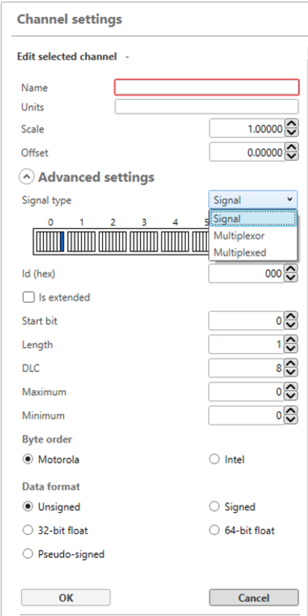
Once the details of the channel setup have been entered, press OK to confirm the changes.
Assigning a CAN channel to an element
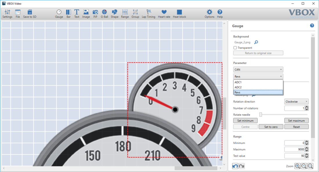
Once the CAN channels have been defined within the CAN settings area, return to the scene designer.
Select the element you wish to assign CAN data to. Within the right-hand panel, under the ‘Parameter’ drop-down list, select ‘CAN’ and then the channel of interest.
Further information on setting up elements can be found here.
Editing a supplied scene file to add a new CAN database
All of the supplied scenes with CAN data displayed (such as RPM, Brake and Throttle) are set up to use data from a Racelogic Micro Input Module.
This can easily be changed within the CAN settings page.
Clear all CAN inputs as shown below.
.png?revision=1)
Turn OFF send acknowledge to avoid any unwanted data being placed onto a vehicle CAN bus.
Now add the new vehicle or RL module channels to log, and reassign any elements in the scene to the new channels - as described above.