Connecting MoTeC devices to VBOX Video HD2

Introduction
CAN data transmitted from MoTeC devices listed below can be received by VBOX Video HD2 and used for producing full-colour HD graphics that are overlaid onto the video in real time, making your videos more exciting and informative. To connect a VBOX Video HD2 system to a MoTeC Data Logger or ECU together, an RLCAB015L unterminated CAN cable is required.
Compatibility:
- MoTeC Data Loggers: C125, C127, C1212, C185, C187, C1812, CDL3, SDL, SDL3, ADL, ADL2, ADL3 and ACL.
- MoTeC M1 Series ECUs (dependent on package).
- MoTeC 'Hundred Series' and M84 ECUs.
In VBOX Video Version 1.5.272 or later and HD2 Firmware Version 1.3.78.1 or later, it is possible for MoTeC customers that use current release version i2 standard or i2Pro software to align HD2 video giving a 2-camera option with fully synchronised data that can be reviewed in MoTeC Data Analysis software.
A MoTeC Data Logger or M1 ECU must be configured to transmit video synchronisation messages to the HD2 via CAN and the HD2 scene must be configured to receive these unique CAN messages.
|
Note: A MoTeC dash may be required to initiate communication with a MoTeC ECU. Contact Racelogic Support for further assistance. |
Configuring the HD2 Scene
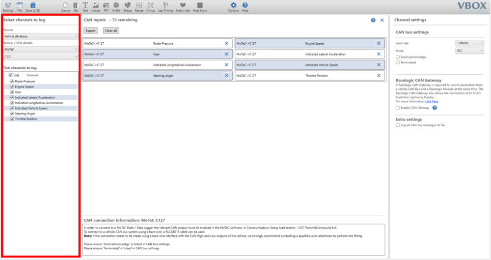
- With the scene file open in VBOX Video, navigate to Settings > CAN.
- Select the Source as Vehicle database, select MoTeC for the Vehicle / ECU details and choose the MoTeC device being used. In the example below the device selected was a C127 Dash Logger. Ensure that the Channel boxes are set to log.
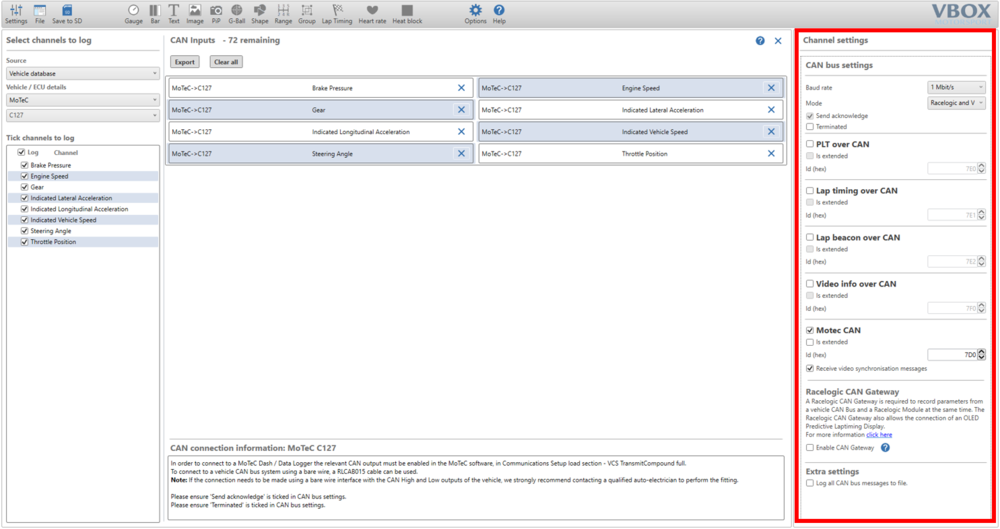
- Select a Baud rate of 1 Mbit/s and the Mode to be Racelogic and VCI. Then tick the Motec CAN box and the Receive video synchronisation messages box as well. The HD2 will send diagnostic data to the MoTeC Data Logger on address 0x7D0 by default, this data includes the HD2 temperature, supply voltage, SD card memory free in MB and recording status.
Note: The sync messages are sent once per minute, so videos that are shorter than one minute will not have sync data and will appear unsynchronised.
- Once you are satisfied with the scene, it can be saved to an SD card using the Save to SD button. Instructions on how to complete the upload to the HD2 Unit can be found here.
Installing MoTeC Dash Manager Software
Dash Manager Software is used for configuration, testing, retrieving the logged data, and for general management of the Logger.
- Go to the MoTeC website at www.motec.com and navigate to Downloads > Software > Latest Releases > Data Acquisition and Displays software.
- Save the selected file in your preferred location (for example desktop).
- When downloading is finished, double click on the file and select Run.
- Follow the instructions on the InstallShield Wizard.
- To start the program after installation, click the Dash Manager icon on the desktop or click Start > All Programs > MoTeC.
Connecting the Data Logger to a PC
The Display Logger connects to the Ethernet port on the PC. This requires a connector for the standard Ethernet cable in the loom.
PC Communications Setup
To enable PC communications, a connection must be setup in the Dash Manager software to match the Display Logger serial number.
- On the Tools menu click Connection Settings and then click Add.
- Click OK to choose IP (Ethernet). This is the only available connection type.
- Click Search*.
- In the list with discovered devices, click the required Display Logger and click Select.
If the PC needs to communicate with more than one Display Logger, repeat the steps.
Notes:
- *The connection uses IPV6, which can be affected by firewall and antivirus applications.
- If you have a Display Logger connected but it is not listed in Discovered Devices, try disabling or uninstalling all anti-virus software.
- If the Device is 'discovered' without the anti-virus software, you can turn it back on and put in appropriate exceptions to allow the Display Logger Manager to communicate with the device.
- Only one connection can be active at a time. To switch to a different Display Logger, click Make Active.
Tip: The current connection is listed at the bottom of the Dash Manager splash screen (this is the main Dash Manager screen with the picture of the Logger).
MoTeC Dash Logger Setup
- Download and save the following MoTeC Communication template to Documents > MoTeC > Dash > Comms Setup folder.
- Using the correct Dash Manager software for your MoTeC Dash Logger, download the configuration by navigating to the Online menu, click Get Configuration to retrieve the current configuration file. This will only be necessary if the original file is not available on the PC.
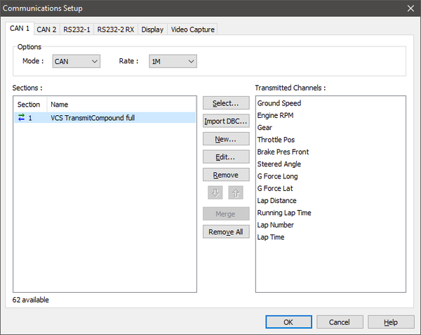
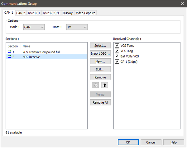
- In Dash Manager, go to Connections > Communications...> CAN which is the CAN port that your Racelogic HD2 unit is connected to. Find an empty CAN slot and click the Select button and select the VCS TransmitCompound full Communication template and click OK. These are the CAN channels being sent from the MoTeC Data Logger to the HD2.
- Repeat Step 3 but select the HD2 Receive Communication template. The CAN port setup should be as shown below. The VCS Temp Channel is the HD2 temperature in °C. The VCS Diag channel is the HD2 Recording status, 0 for Not Recording or 1 for Recording. The Bat Volts VCS is the HD2 supply voltage. The GP1 (3 dps) is the SD card memory free in MB.
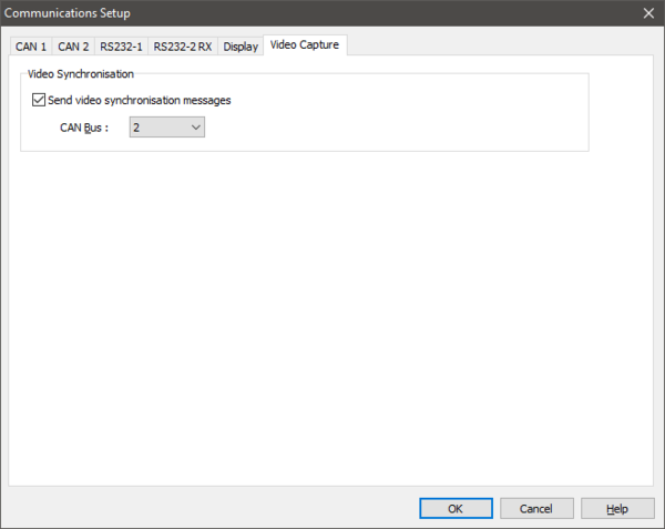
- In Dash Manager, go to Connections > Communications... > Video Capture. Tick the option to Send video synchronisation messages and select the applicable CAN bus. In the example below it has been set to CAN bus 2.
Note: The sync messages are sent once per minute, so videos that are shorter than one minute will not have sync data and will appear unsynchronised.
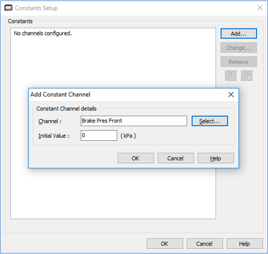
- Ensure that all channels being sent are generated. If a channel is not being generated in your configuration, set the channel as a constant as shown in the example below then send the configuration to your Dash.
MoTeC M1 Series ECU Setup
The method described here is based on Version 1.4 M1 Tune software. Ensure that the package you are using is compatible with a VCS.
- Open MoTeC M1 Tune and open a Package.
- Click the All Calibrate Worksheet.
- Search for VCS as shown below.
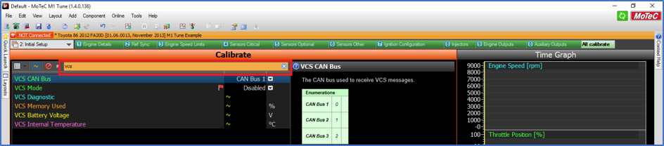
- Click on the dropdown menu for VCS CAN Bus and set this to the CAN Bus that is connecting the M1 ECU to the VBOX Video HD2.
- Click on the dropdown menu for VCS Mode and set to Enabled.
Configuring a MoTeC 'Hundred Series' ECU
The method described here is based on Version 3 ECU Manager software. Configuration in Version 2 ECU Manager software will be very similar.
- Open MoTeC ECU Manager and open a file.
- On the Adjust menu, click General Setup.
- Click Communications and then click Setup Custom Data Sets.
- Click the Custom Set 2 tab.
- Click Add to add the following channels (in this order):
- Ground Speed
- RPM
- Gear
- Throttle Position
- Brake Pressure or Longitudinal G Force
Note: Use Longitudinal G Force only if Brake Pressure is not available in the ECU. If any of these channels are not available in the ECU, they will not be displayed on the video overlay.
- Click OK.
- On CAN Setup, select CAN 0 Data and enter 7 (Custom Data Set 2 Compound Tx).
Note: If CAN 0 is already in use, then complete the set up on CAN 1. - Select CAN 0 Address and enter 31.
- Select CAN 0 Transfer Rate and enter 100.
MoTeC M84 ECU Setup
The method described here is based on M84 Version 1.2 ECU Manager software.
- Open MoTeC ECU Manager and open a file.
- On the Adjust menu, click General Setup.
- Click Communications and then click CAN Setup.
- Select VCS/PDM CAN Address and enter 31.
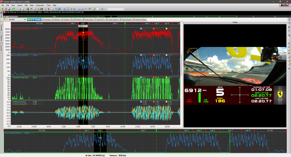
Viewing HD2 Video and MoTeC Data in i2 Data Analysis Software
MoTeC's i2 data analysis software is used to analyse the logged data that has been recorded by the Display Logger. Any number and combination of graphs, gauges and reports can be analysed simultaneously with HD2 video.
To automatically align logged data with video, the HD2 video file must be copied from the SD card onto the laptop into a specific folder. Then when the data is downloaded from the Data Logger and opened in i2 will then scan the folder to find the HD2 video file that matches the logged data. This will work even if there are multiple video files for the same data file.
Installing i2 Standard and i2 Pro Software
- Go to the MoTeC website at www.motec.com and navigate to Downloads > Software > Latest Releases > i2 Standard or Pro software.
- Save the selected file in your preferred location (for example desktop).
- When downloading is finished, double click on the file and select run.
- Follow the instructions on the InstallShield Wizard.
- To start the program after installation, click the i2 Standard or i2 Pro icon on the desktop or click Start > All Programs > MoTeC > i2 Standard or i2 Pro.
Copy the Video Files into the Video Folder
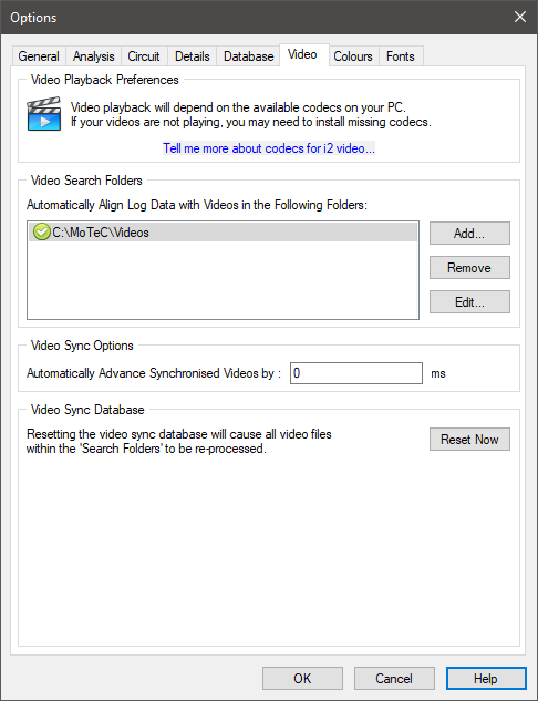
Copy the video files into the specified videos folder set in i2 Standard or i2 Pro. To determine which video folder has been configured, open i2, go to Tools > Options and click the Video tab as shown below. The default folder is C:\MoTeC\Videos. You can Add, Remove or Edit folders in the list if required.
Retrieving Logged Data
To extract the logged data from the logging device via i2, on the File menu, click Get Logged Data. i2 will list all device types that have configuration programs installed on the computer allowing the appropriate device to be selected.
Note: If multiple versions of the device configuration software are installed then i2 will run the latest version of the configuration software for that device. If a different version is required, then the device configuration software should be run separately.
Adding a Video Element to Worksheet
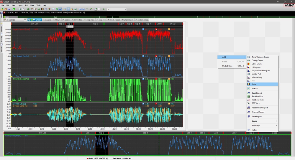
- To display a video with data in, i2 requires a worksheet to be modified. Change the size of the Graph element in a worksheet and then right click Add > Video to add a Video element to the i2 Worksheet.
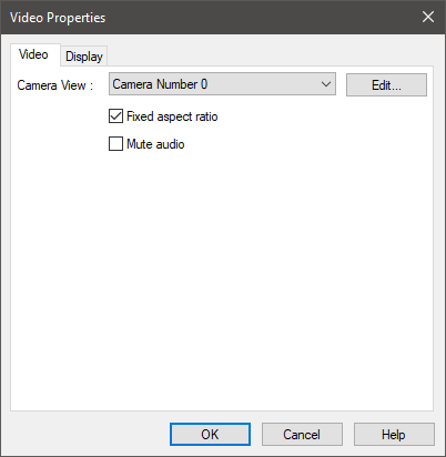
- The camera view should display Camera Number 0, this shows that i2 has successfully aligned the data and video. Click OK in the Video Properties Menu.
- Below you can see that there is no video recorded at the cursor position, by moving the cursor to an outing time which has video will then display video footage.
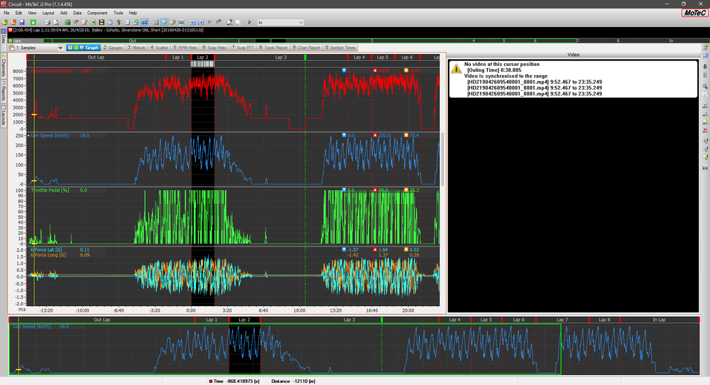
- By clicking on the Video element and pressing the ‘A’ key, the data and video will now play together, to stop the animation press ‘A’ again. By scrolling through the data using the cursor the video will be aligned with the data trace this is particularly evident if you have CAN channels displayed on the overlaid Video gauges.