08 - PT / DT Channel and Axis Setup
For each channel there are a number of attributes that can be configured, including those relating to the y-axis. These are configured in the Channel Set-up and Axis Set-up screens, which are accessed by double-clicking on any of the channels in the data table or by right clicking the mouse button and selecting the ‘Channel scaling & Axis setup’ option, or by clicking the ‘Graph Set-up’ icon on the Toolbar.
Channel Setup
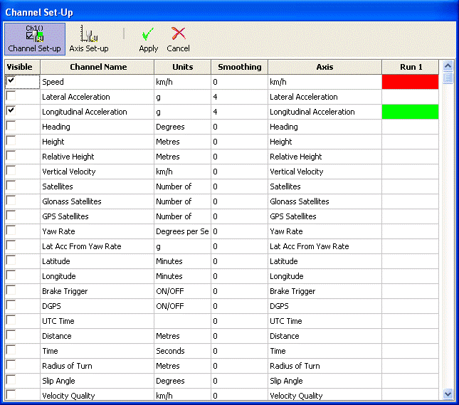
Column descriptions:
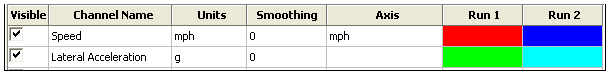
Visible
The tick boxes in this column switch individual channels on or off in the graph window.
Channel Name
This column contains the names of the available channels.
Units
Shows the units of each of the available channel.
Smoothing
In this column a smoothing level can be applied to each channel individually. This can be useful for the Longitudinal and Lateral Acceleration channels. The smoothing level number directly relates to the number of samples used in the smoothing routine – the higher the value the smoother the trace will appear on the screen, but it will become less representative of the response of the vehicle as it was actually recorded:
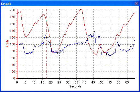
The example above shows the Lateral Acceleration channel with a smoothing level of 2.
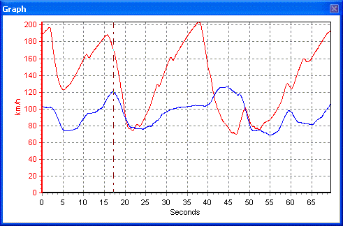
This example shows the Lateral Acceleration channel with a smoothing level of 25 – note how the individual peaks and troughs are no longer present, so the true dynamic values of the vehicle are now not shown. Smoothing Level should therefore be carefully applied – too little and the data can be too ‘noisy’ for easy analysis; too much and valuable information can be lost.
Axis
Displays the axis with which the channel is associated. To change the associated axis, click the mouse in the right hand end of the axis box once the channel has been made visible. A common application for this is to display both the Longitudinal and Lateral Acceleration channels, but to have them referring to one axis only:
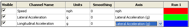
Run 1
This column shows the selected colour for each active channel. To change the colour click on the colour box of the channel and select a new colour from the colour selection box that appears. The colour chosen will also be applied to the axis, should this be selected; for example, if the Lateral Acceleration channel is used in green, so too will the Lateral Acceleration axis, if it is used.
If compare files are also loaded then Run2, Run3 etc columns will be present in which the colours of these compare file channels can be set:
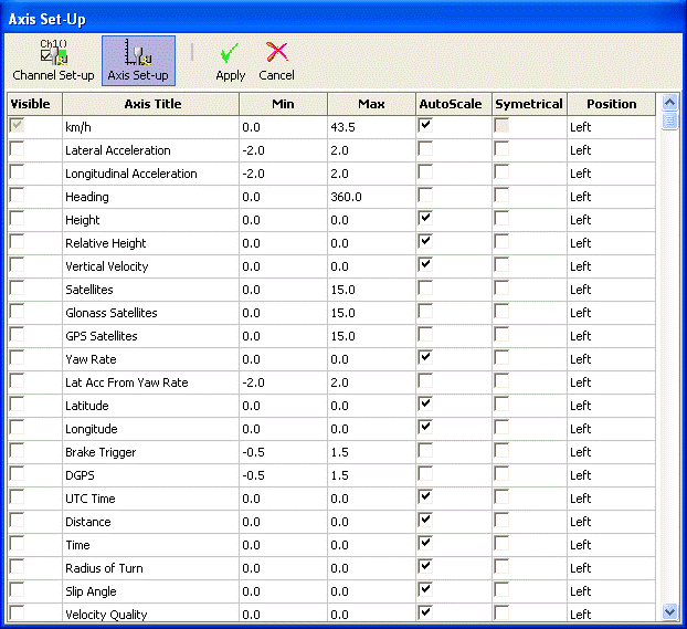
Axis Setup
The Axis Setup window contains all the controls needed for assigning and configuring the y-axis of the Graph screen:
Column descriptions:
Visible
Each tick box in this column switches an individual axis on or off in the graph window.
Axis Title
Shows the title of each available axis. The axis title is edited by clicking on the box and entering a new name.
Min / Max
The Min and Max boxes allow the scale ranges for each axis to be set.
Autoscale
The autoscale option causes the axis scales to automatically fit the minimum and maximum values of the loaded channel.
Symmetrical
This option will cause the positive and negative maximum values on the axis to be the same magnitude. The magnitude of these will be determined by the largest positive or negative value of the channel.
Position
This option controls whether the channel axis appears at the left or right of the Graph window.