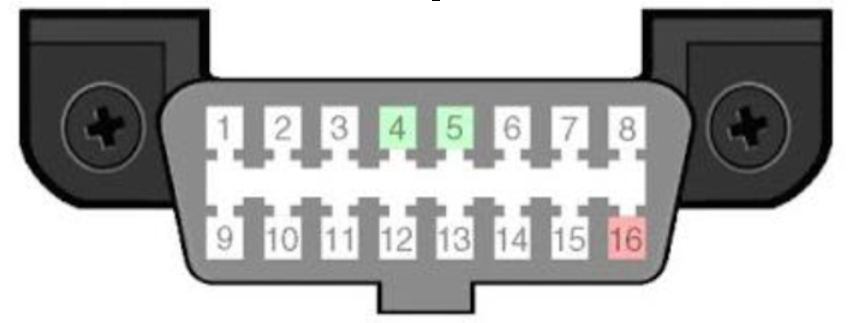
OBDII Port Pinout Arrangement
In order to capture data from a vehicle CAN bus system, a VBOX must have:
- The correct vehicle specific CAN database loaded into the scene file.
- A successful hardware connection into the vehicle's CAN bus.
A hardware connection can be achieved via an OBDII (On-Board Diagnostics) port, available on some vehicles, as long as it is outputting CAN data.
Most vehicles supplied with an OBDII port will have a standard CAN pinout arrangement (CAN High: Pin 6; CAN Low: Pin 14), however some vehicles will have differing pinout arrangements, as indicated in the diagram below:

| 1 | Tesla/McLaren CAN Hi | 9 | Tesla/McLaren CAN Low |
| 2 | SAE J1850 + | 10 | SAE J1850 – |
| 3 | Ford HS2 CAN Hi | 11 | Ford HS2 CAN Low |
| 4 | Chassis Ground | 12 | Nissan CAN I |
| 5 | Signal Ground | 13 | Nissan CAN I |
| 6 | Standard CAN Hi | 14 | Standard CAN Low |
| 7 | K-Line | 15 | L-Line |
| 8 | 16 | 12 V + |
If your vehicle does Not have a standard OBDII port CAN pinout arrangement, the VBOX to OBDII connector you are using will need to have the OBDII pin arrangement rewired to the correct CAN High and Low format. Racelogic may be able to supply you with a custom OBDII connector cable with CAN High and Low wired to the correct pins for your vehicle, please contact support@racelogic.co.uk for assistance.
