How to measure CAN bus Baud rate using an oscilloscope
- Last updated
-
-
Save as PDF
-
Setting the correct baud rate within the VBOX is essential, if the VBOX is not configured to the correct CAN baud rate it will not detect the messages present on the bus.
To determine the baud rate using an oscilloscope you will need to do the following:
- Locate your vehicles CAN bus, some vehicle CAN bus locations can be found in our CAN database.
|
.jpg?revision=1)
|
- Connect a scope probe to a single CAN wire, using either a Pomona test clip, pictured above, or by carefully stripping back a small section of wire casing, being careful not to damage the wire inside.
|
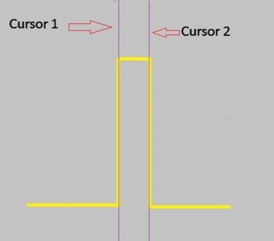
- Depending on the capability of your scope, you need to zoom in on a single ‘bit’, this will be the smallest peak on the scope, as indicated on this image.
|
.jpg?revision=1)
|
- Once you have zoomed in on this part of the readout, you will need to use the cursor measure tool to measure the transmission frequency.
|
.jpg?revision=1)
|
- The ‘Delta time’ should be displayed down one side (depending on the model of your scope) and this will hopefully show a transmission frequency in kHz, this will be your baud rate. (e.g 500 kHz = Baud rate of 500 kbit/s)
You can then use this information to correctly set up the CAN baud rate when setting up your VBOX.
|