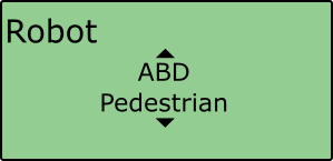
ABD Pedestrian
Alongside ABD’s Pedestrian system, the pedestrian mode allows the live calculation of ADAS parameters between the subject vehicle and the pedestrian dummy. For a successful test, there needs to be an allocated ‘Target’ VBOX which is placed trackside and connected to the Pedestrian rig and a ‘Subject’ VBOX which is placed on board the Vehicle.
Subject
Hardware configuration
For successful integration with the pedestrian system, the user will need the following equipment in the Subject Vehicle:
- 1 x VB3iD-RTK system (with both GPS antennas connected and placed 1 m apart*)
- 1 x IMU04 (connected to the VBOX via the RLCAB119)
- 1 x IMU Roof Mount
- 1 x DGPS Radio and antenna
- 1 x ADAS vehicle to vehicle communication radio and antenna
VBOX Manager Configuration
Enabling ABD Pedestrian Mode
- Connect VBOX Manager to the VBOX.
- Enter the 'SETUP' menu of VBOX Manager.
- Select the 'Robot Modes' option and choose 'Configure'.
 |
 |
- Scroll to 'ABD Pedestrian', select and then choose 'Subject'.
 |
 |
 |
 |
Configuration Settings
Selecting the ‘ABD Pedestrian - Subject' option within VBOX Manager will automatically configure the VBOX to work with the ABD pedestrian system by applying the following settings:
- Dynamic Mode – 'High'
- Hi Dynamic KF – 'Disabled'
- ADAS Mode – '1 Target - Subject'
- Log Rate – '100 Hz'
- DGPS Mode – 'RTCM v3*'
- Dual Antenna Mode – 'Enabled'
- Dual Antenna Orientation – 'Pitch Mode'
- Dual Antenna Separation – '1.000 m**'
- IMU Integration – 'Enabled'
- IMU Roof Mount – 'Enabled'
- VCI CAN Rate – '500 kbit/s'
- VCI CAN bus – 'RS232 port'
- VCI Termination – 'Enabled’
- The following CAN IDs will also be switched on, more information on these is available here:-
- 309
- 314
*Please note that the user must manually select the correct DGPS serial rate that relates to the radio system they are using.
**1.000 m is the default dual antenna separation. If it is not possible to gain a 1 m separation, then the user will have to enter the required separation value in the 'Dual Antenna' area of VBOX Manager.
Setting the Datum
Within the Subject VBOX, it is possible to set a ‘Datum’ point that will be the ‘Zero’ point of the test. To do this, the user must move the vehicle into contact with the Pedestrian target and select the ‘Set Datum’ option from VBOX Manager.
Note: The ADAS contact points must be set BEFORE setting the Datum point.
 |
|
|
Setting the Reference Heading
Once a Datum point has been set, the user then needs to define the test heading. This is done by driving back down the test track and selecting ‘Set Heading Ref.’ when in position.
This reference heading is then used by ABD to define the orientation of their local coordinate frame and is calculated from the Heading reference point through to the Datum point.
 |
|
|
Target
Hardware Configuration
For successful integration with the pedestrian system, the user will need the following equipment in the Target Vehicle: -
- 1 x VB3i system (Any VB3i Variant is acceptable)
- 1 x ADAS vehicle to vehicle communication radio and antenna
VBOX Manager Configuration
- Connect VBOX Manager to the VBOX.
- Enter the 'SETUP' menu of VBOX Manager.
- Select the 'Robot Modes' option and choose 'Configure'.
|
|
- Scroll to 'ABD Pedestrian', select and then choose 'Target'
|
 |
|
|
Configuration Settings
Selecting the ‘ABD Pedestrian - Target' option within VBOX Manager will automatically configure the VBOX to work with the ABD pedestrian system by applying the following settings:
- Dynamic Mode – 'High'
- Hi Dynamic KF – 'Disabled'
- Log Rate – '100 Hz'
- ADAS Mode – '1 Target - Target'
- Dual Antenna Mode – 'Disabled'
- IMU Integration – 'Disabled'
- VCI CAN input:
- RefX_pos – CAN id 647 start bit 0, length 32, Intel, Signed integer, scale 0.001
- RefY_pos – CAN id 647 start bit 32, length 32, Intel, Signed integer, scale 0.001
- VCI CAN Rate – '500 kbit/s'
- VCI CAN bus – 'RS232 port'
- VCI Termination – 'Enabled’
- The following CAN IDs will also be switched on, more information on these is available here:-
- 308
- 309
- 314
Sync to target
Once the Datum and Reference heading have been set, it is possible to send this information to the Target VBOX by pressing the ‘Sync to target' option within VBOX Manager.
Doing this will automatically update the Target Vehicles position to the latitude and longitude of the Datum point.
 |
|
|
Target VBOX Functionality
The Target VBOX remains stationary at the side of the ABD pedestrian rig, with the output position being the Datum point that has been previously set.
By connecting the CAN out of the ABD system to the VBOX VCI port, the Target VBOX position will update by the correct amount based on the x and y offset being sent from the ABD rig.
This positon is then sent via the radio link to the Subject VBOX to allow the calculation of live ADAS parameters.
The target VBOX does NOT use it’s own position and so the robot mode should be set to ‘Off’ before being used for another application