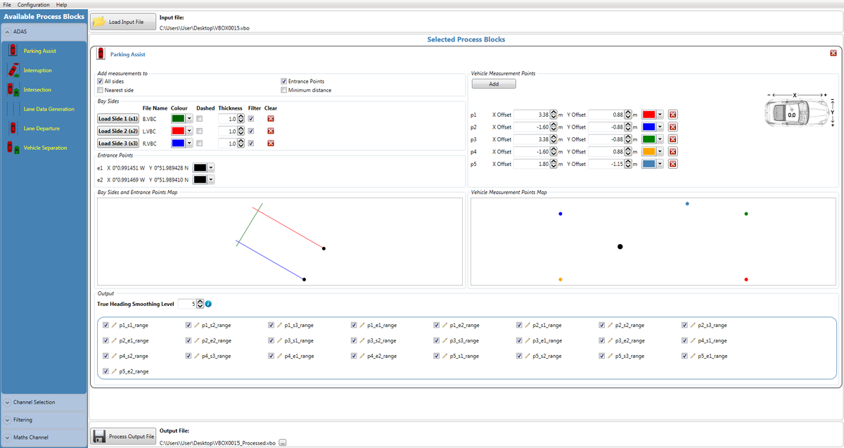
VBOX File Processor - Park Assist

VBOX File Processor Parking Plugin is designed to meet ISO regulation 204/WG14 ISO16787 ‘Assisted Parking Systems (APS) — parking with reference to other parked vehicles’.
Requirements
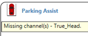
Input source files must contain true heading information in order to be compatible. This means that the Parking Assist plugin will work with files from VB3i SL RTK units only.
An error message will show if the true heading channel is missing from input file, and the software won’t allow the user to process a file.
.png?revision=1)
Smoothing can be added to the true heading channel if the raw input data is noisy. Here the user can set the number of samples the data channel is smoothed over – the default value is 5.
.png?revision=1)
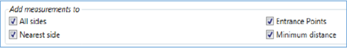
Add measurements to
This section selects which channels are included in the resulting output file.
.png?revision=1)
- All sides - Denotes that a measurement to each bay side should be added for each point on the vehicle.
- Nearest side - Denotes that a measurement to the nearest side should be added for each point on the vehicle.
Note: If all sides is also ticked, one of the sides will contain the same data as the nearest side channel for a given vehicle point. - Entrance points - Includes a measurement to both entrance points from each vehicle point.
- Minimum distance - Denotes that a single channel should be added containing the minimum vehicle point to bay side measurement (effectively the minimum distance from the vehicle to any side).
Bay side configuration
Parking assist can be used to create any virtual 3 sided parking bay, for use with reverse or parallel parking tests.
A bay must be configured from 3 separate files that have to be plotted by the user. The user cannot create a bay from a single logged file.
Input files can be .vbo (VBOX), .vbc (lane departure), or .dbn (PB/DB/VBM).
.png?revision=1)
When a file with more than two position points is loaded, parking assist plugin will produce a line of best fit through the position points within the loaded file. This ensures the bay sides are straight.
.png?revision=1)
| When plotting (recording) a bay side, the user is required to extend the plot of the bay side past the corner point, so that there is a clear overlap. When configuring the sides of a bay, ensure the plotting of the bay starts from the entry point, and finishes past the intersection of the ‘base’ bay line.
The overlap of plotted lines is required as the software determines the ‘base’ of the bay as the side with 2 overlapping lines/intersections (green line in case picture to the right).
Once there are 3 overlapping lines the software will automatically determine 2 entry points for the lane, taking the furthest point from intersection. For this reason the customer should ensure they do not plot too far past the corner point of the lane.
Customers can use the ‘bay sides and entrance points map’ to visualise (check) the configured bay. Within here, the user is able to change the colour, appearance and define thickness of the visual representation. This is only a visual representation, and has no bearing on the actual result (i.e. thickness of line does not alter result). |
.png?revision=1) |
Complex Shape configuration
|
In software version 1.13.19.853 and later it is possible to add complex shapes instead of straight lines for bay sides. This allows for testing when there are no parking bay lines and perhaps only vehicles.
In the example, 2 vehicles sides were surveyed and are located either side of the parking space of interest. It is important to turn the filter off so that details such as the wing mirrors can be included in the measurement distance calculations.
Please note that as there are no longer Entrance points, these channels will not be output in the processed files. |
.png?revision=1) |
Vehicle measurement point configuration
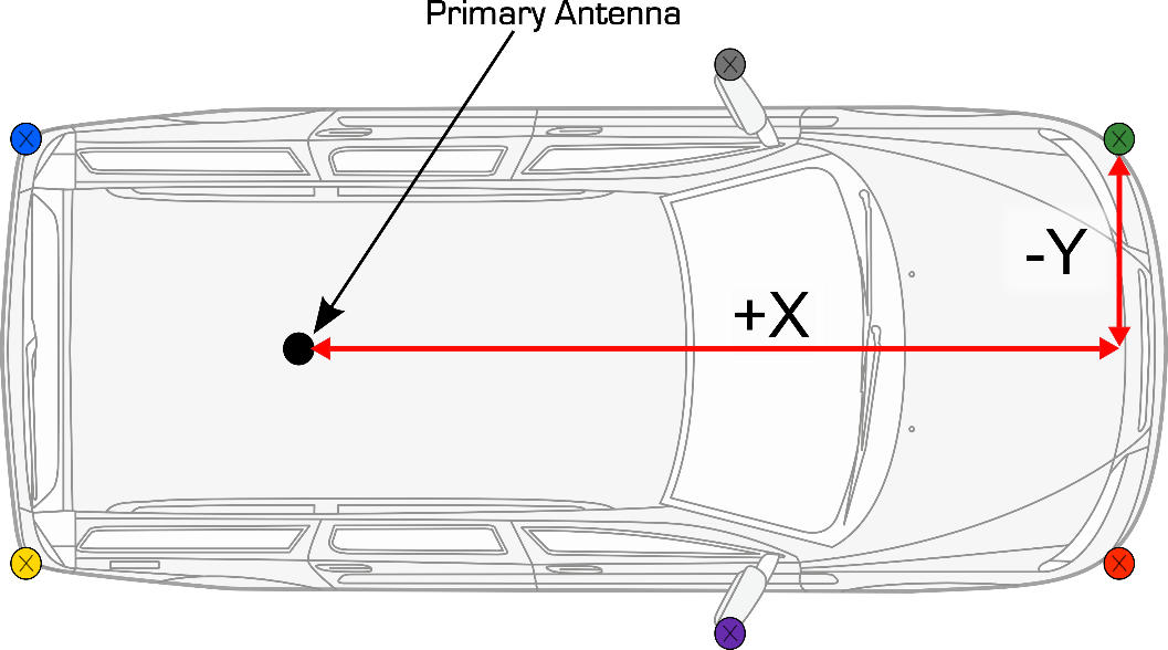
The vehicle measurement points section allows the user to configure required vehicle measurement points.
There is no limit to the number of vehicle measurement points that can be set.
Points should be measured from the primary antenna as shown below.
There is a ‘vehicle measurement points’ map to visualise the defined measurement points. As with bay sides the visual lines can be altered by colour to make it clear which point of the car the data (i.e. p1) is referencing in the processed result.
Each configured point will produce 5 range channels, two relative to entry points, and three relative to the bay sides.
.png?revision=1)
Results
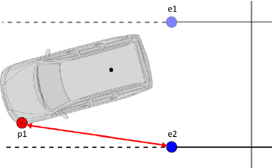
e1 and e2 measurementsThe 2 range measurements to bay side entrance points are direct straight line ranges between vehicle and entry point. The created channels will be labelled e1 and e2 relative to what is shown in the ‘bay sides and entrance points’ map. Two measurements in relation to the bay side entrance points will exist for every vehicle measurement point. For example, the p1_e2 measurement is the distance between the second entry point and the first defined vehicle measurement point. |
|
s1, s2 and s3 measurementsThe 3 bay side range measurements are calculated perpendicular to the bay side headings. The created channels will be labelled s1, s2 and s3 relative to what is shown in the ‘bay side and entrance points’ map. Three points in relation to the bay sides will exist for every vehicle measurement point. For example, the p1_s3 measurement is the range of the first defined vehicle measurement point to bay side 3. |
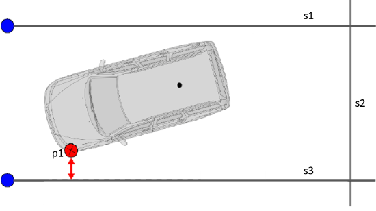 |
Pre Software version 1.13.19.853If the vehicle is outside of the configured bay, the bay side range measurements are calculated perpendicular to the extended bay side headings. Please note that as all range values are absolute values, they have no signing. |
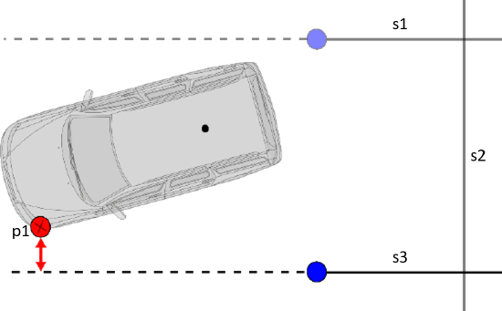 |
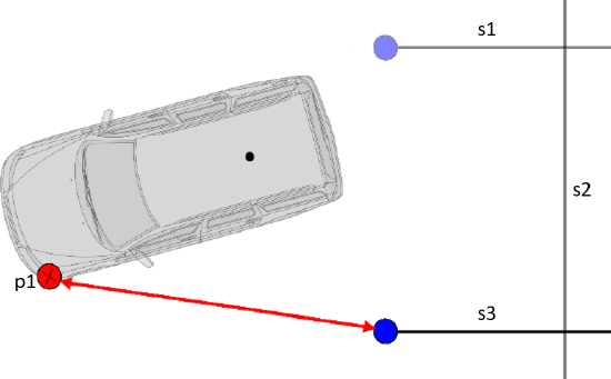
Software version 1.13.19.853 and laterIf the vehicle is outside of the configured bay, the bay side range measurements are calculated to the closest bay side point (i.e. the entrance point).
Note: As all range values are absolute values, they have no signing. |
 |
Configuration and Processing
.png?revision=1)
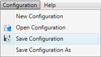
Combined bay sides and vehicle measure point configuration can be saved and reloaded at later date, using configuration/save configuration. Note that plugin settings are saved as a whole file, so separated vehicle measurement points and bay side profiles cannot be loaded.
As the plugin uses true heading, all range reference values will remain valid whether the vehicle is driving towards, or moving away from the bay.
Prior to processing the files, the user is able to alter what channels are processed, along with changing the naming conventions to make them suit their own needs.
.png?revision=1)
Licensing
All process blocks within VBOX File Processor are free of charge. However, ADAS plugins require 'free' registration.