FCW - Static Point (Static Base)

The Static Point feature of the VB3iSL-RTK firmware allows the user to set any arbitrary target point as the static reference point for all positional calculations. This facility can be used when a dummy pedestrian or static vehicle is the test target.
This also requires the use of a static Racelogic Base Station to ensure position accuracies of up to 2 cm.
Hardware Configuration
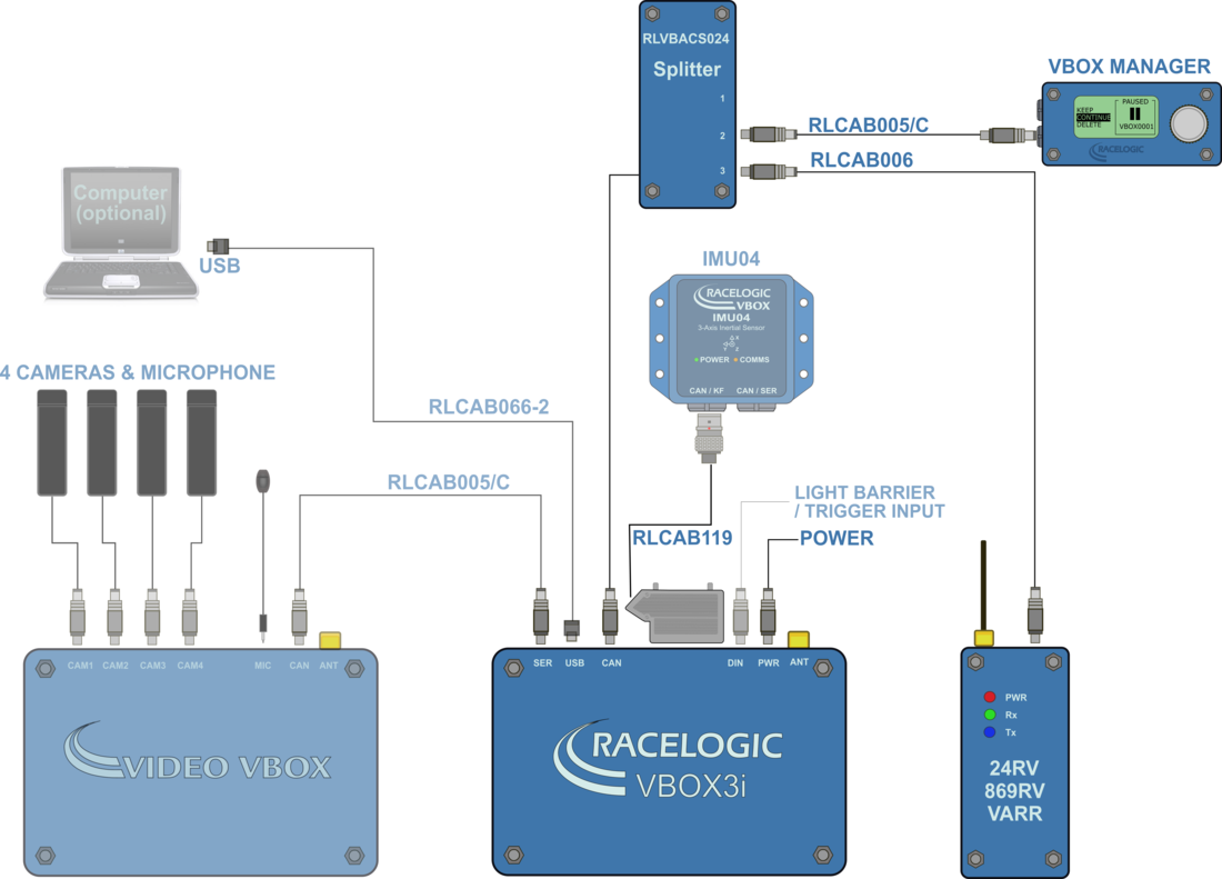
The following diagram shows the hardware configuration required for Static Point testing. The items greyed out are not essential to run this test but many customers will find them a useful addition.
Connection between the VB3i and computer should be made via USB or Bluetooth to ensure optimum performance.
Please ensure that all vehicle antennas are correctly positioned and connected.
VBOX Configuration
Subject Vehicle1. Connect VBOX Manager to the VBOX in the Subject Vehicle. |
| 2. Enter the setup menu of VBOX Manager. |
| 3. Select the 'VBOX' option. |
4. Select 'LOG RATE' and set the rate to '100 Hz', then select 'BACK' to return to the 'VBOX' setup menu..png?revision=1) |
5. Select 'DYNAMICS' and set the dynamic mode to 'NORMAL', this Dynamics mode is best for ADAS tests, return to the 'VBOX' setup menu..png?revision=1) |
|
6. Select 'DGPS' and set the DGPS mode to the same 2 cm mode that the Base Station is set to, return to the 'VBOX' setup menu. For further info on RTK modes see RTK Configuration. .png?revision=1) |
|
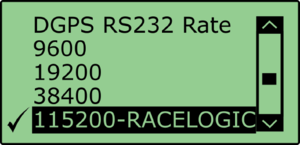
7. Select 'DGPS RS232 Rate' and select the appropriate settings for your radios, return to the VBOX setup menu. Note: To ensure that the VBOX receives the DGPS correction signal, the correct RS232 rate must be set. All Racelogic blue boxed radios use 115200 kbit/s, Satel grey boxed radios use either 19200 kbit/s or 38400 kbit/s. |
|
8. Return to the main setup menu and select the 'ADAS' option, then select 'STATIC POINT' mode. |
.png?revision=1)
Base StationA static Base Station must be used for the VBOX to gain the RTK 2 cm positional accuracy. Moving Base cannot be used because a static Base Station is the only way to create a reference to a fixed point like a nominated static point. See the Base Station user guide for Base Station installation. Important Note: The Base Station GPS antenna must be in exactly the same location for marking the static point and for subsequent testing. It is also good practice to save the location into the Base Station memory. |
|
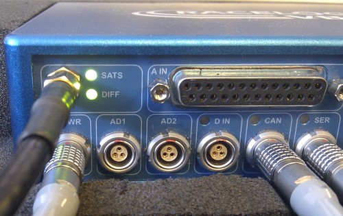
The VBOX front panel will indicate the required RTK Fixed status, with the illumination in green of the 'DIFF' light.
|
Pre-test Configuration
Setting the ‘Static Point’1. Position the vehicle touching the desired location of the Static Point. |
.png?revision=1) |
|
2. Within the 'STATIC POINT' menu select the 'SET' option. This sets the location of the Static Point. |
|
|
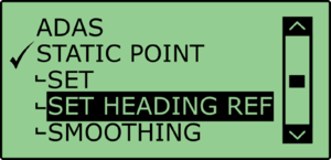
3. Once the Static Point has been set, drive the vehicle away in a straight line along the test track to a distance of over 100 m. Select 'SET HEADING REF'. |
.png?revision=1)
Smoothing LevelsThere are two configurable variables linked to heading smoothing; ‘Smoothing Distance’ and ‘Speed Threshold’. Due to the nature of the vehicle separation measurement and calculation process many channel are derived using the heading of the vehicle which can be noisy. To overcome this the heading can be smoothed with a dynamic smoothing routine. Using VBOX Manager, go to the 'ADAS' menu and go to the 'STATIC POINT' menu and select 'SMOOTHING'. |
Smoothing DistanceThe smoothing routine is calculated between the current and previous samples. The previous sample to be used is determined using a Smoothing Distance, this results in a variable number of samples used to determine the smoothing level on the heading; the lower the speed the more samples that are used. With 100 Hz logging and a smoothing distance of 1.1 m at 80 km/h the heading is calculated over the previous 5 samples whilst at 15 km/h the heading is calculated over the previous 26 samples. |
Select ‘SMOOTHING DIST’ and enter the smoothing option between 0.00 m and 2.00 m. A smoothing distance of 1.00 m is recommended..png?revision=1) |
Speed ThresholdDue to the large number of sample in a small distance when travelling at low speed the heading channel can become very noisy, this in turn results in many of the Vehicle Separation channels becoming noisy at low speed. When the speed threshold is set to a certain speed the heading is locked when the vehicle travels under that speed. |
1. To set the speed threshold repeat steps above in 'Smoothing Levels', then select 'SPD THRESHOLD' and enter the speed threshold option..png?revision=1) |
| 2. We recommend a Speed Threshold of 5 km/h. |
.png?revision=1)