Screen Layout - MFD Touch
As the name suggests, you can control the MFD Touch by using the capacitive touch screen.
The top of the screen contains generally contains indicative status information.
The centre of the screen contains mode/settings information that you can navigate by pressing the forward/ back buttons or by swiping left or right on the screen.
The bottom of the screen contains function buttons.
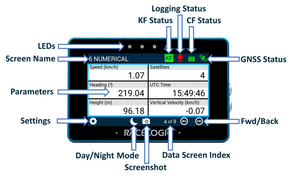
KF Status
If you enable IMU Integration in the connected VBOX 3i/3iS unit, MFD Touch will display the current IMU Kalman Filter status of that connected unit. The Kalman Filter Status Icon reflects the IMU LED on the VBOX 3i/3iS front panel.
The icon has the following different statuses:
| Solid orange indicates that IMU integration has been enabled but that the detected IMU is invalid. When you use an IMU04, make sure that it is; connected with an RLCAB119 to the 25-way D connector, is set to Racelogic CAN mode, and is running the latest release of the firmware. |  |
Flashing green indicates that the initialisation is complete but that movement is not detected yet. |  |
| Flashing orange shows that the IMU is connected and that the integration initialisation is running. This will not complete until the VBOX 3i/3iS has had a satellite lock while being stationary for 30 seconds. | |
Solid green indicates that movement is detected and that the IMU integration is working. | |
Logging Status
Note: When using VBOX 3i units only
The Record icon shows the current logging status of the connected VBOX unit.
| When VBOX is logging data to the inserted CF card, the icon will be red. |  |
| When the unit is not logging data, the icon will be grey. |  |
When a CF card is detected and available within the VBOX (i.e. the CF Status icon is green), logging can also be controlled by pressing the Record Icon. If 'Logging Beep' is enabled in the General Settings menu, the unit will make an audible alert signal when the logging state of the connected VBOX unit changes.
If the grey Record Icon is pressed when the VBOX has its log mode set to ‘Log when moving’ and the vehicle is stationary, the screen title will be briefly display an 'ARMED' status. This indicates that the recording media has been detected, and the unit is waiting for starting conditions to be met before logging commences. When logging commences, the Record Icon will display as red.
If you press the grey Record icon when the unit is not detecting a CF card or if the media is full (i.e. the CF Status icon is red), the unit will emit an audible beep and display one of the following messages:
- NO MEDIA AVAILABLE - No detected recordable media.
- CARD FULL - Media detected but no logging capacity remains.
- NO MEDIA AVAILABLE - VBOX 3i is unable to write to recordable media (i.e. corrupt card).
If MFD Touch cannot detect a VBOX unit, it will display a 'NO CAN' message in this area. A Logging Status channel is also available for selection as a text parameter which will describe the current logging status of the connected VBOX.
CF Status
Note: When using VBOX 3i units only
The CF Status Icon displays the status of the VBOX recording media.
| When a CF card has been inserted into the VBOX and has free space, it will be green. |  |
| If it cannot detect a CF card, the media memory is full, or the VBOX unit is unable to write to the media (corrupt card), the icon will be red. |  |
| If it cannot detect a VBOX unit, you will see a 'NO CAN' message displayed in this area. | NO CAN |
GNSS Status
The Satellite icon displays the current GNSS status of the connected VBOX unit.
 |
Flashing Red No satellite lock/ IMU Coast (Solution Types 0 or 6) |
 |
Solid Green Standalone positional accuracy/ SBAS and Base Station DGPS corrections (Solution Types 1 or 2) |
 |
Solid Orange RTK Float (Solution Type 3) |
 |
Solid Purple RTK Fixed (Solution Type 4). |
 |
Solid White Robot Position, local co-ordinates (Solution Type 5) |
 |
If there is a valid dual antenna lock, a superscript '2' will appear next to the relevant GNSS status icon. |
| NO CAN | If it cannot detect a VBOX unit, you will see a 'NO CAN' message displayed in this area. |
Screen Name
This header shows the name of the current parameter screen. You can change this by pressing and holding or double-tapping the existing screen name. You can find more information on this here.
Parameters
This area will display defined parameters dependent on which screen you are currently on. You can find more information on how to configure these here.
Settings Button
| The Settings Button opens a Settings area for VBOX Display, Decel Test Settings, Accel Test Settings and Lap Timing Settings, along with the ability to save and load settings to and from the SD card. |  |
Forward/Back Buttons
| You can use the Forward and Back arrow buttons to navigate through the different parameter screens. You can also swipe left or right on the screen. |   |
Confirm button
|
Press the Confirm button at the bottom right of the screen to confirm your selection. |
 |
Cancel Button
| Press the Cancel button at the bottom left of the screen to return to the previous screen without saving. |  |
Exit Button
| Press the Exit button to leave the current screen and go back to the previous one. |  |
Day/Night Mode Button
|
You can enable Night Mode by tapping the Moon icon on the bottom of any screen and the colour scheme will invert to suit night-time operation. When you are in Night Mode, you can tap the Moon icon again to revert back to Day Mode.
|
 |
_Night_Mode.png?revision=1)
Night Mode example
Screenshot
|
Selecting the Screenshot button will save an image of what you see displayed on the screen to the inserted SD card. If the screenshot saves successfully, the LEDs will illuminate yellow in sequence from left to right (the progress of writing to the SD card). You will hear an audible confirmation notification when the screen capture is complete. If you were unsuccessful in saving the screenshot (if you did not insert an SD card or the card was full), you see 'NO SD CARD' appear at the top of the screen. The LEDs will flash red 2 times and you will hear an audible error notification. A captured image is saved as a 1.5 MB bitmap image, orientated at 90° to the original screen image, with the prefix 'screenshot'. |
 |
IMPORTANT
NEVER remove the SD card while you capture a screenshot with the unit, as it could cause it to crash!