02 - TC8 Configuration

Hardware connection
Configuration of the TC8 is performed using VBOX Setup software. Using the supplied RLCAB001 cable, connect the serial port on the TC8 to the computers 9 way D serial port – this can be done via a serial > USB converter if required.
Software connection
Use the drop down list to select the correct COM port that the speed sensor is connected to. Click the connect button to enter the TC8 setup screen.
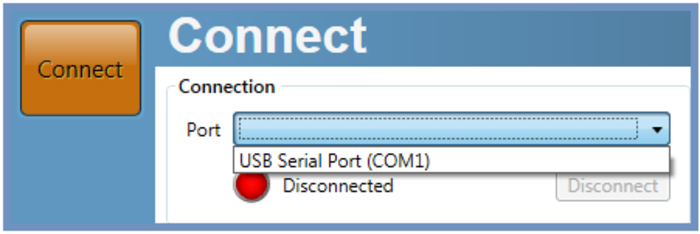.png?revision=1)
Configuring the TC8 using Racelogic Config
General
.png?revision=1)
- Connection - Selected com port, refresh and disconnect buttons.
- Module Information - Serial number and installed firmware version of connected unit.
- Load/Save - Load/Save settings from/into a Racelogic setting file (.RSF). This allows setups to be kept for future use.
- Language - Select an operating language.
- Write to unit - After making changes to setup, the write to unit button must be selected to upload settings.
Settings
.png?revision=1)
- Baud Rate - Baud Rate sets the bit rate of the CAN messages.
Selectable baud rate options are:
1000 kbit/s
500 kbit/s (default)
250 kbit/s
125 kbit/s
- Data Format - This option allows you to change the format in which data is transmitted in stand-alone mode.
-
Modes - In the settings tab, the user has the option to configure the TC8 into one of three CAN modes to suit different applications.
Racelogic Polled - This mode should be set if the module is to be used with a Racelogic VBOX. All the CAN parameters are set to work with the Racelogic VBOX CAN protocol. In this mode no other parameters need be set or indeed will have any effect.User Polled - This mode allows a customer’s own data logging system to poll the module for data using the CAN bus. In this way, the output timing of the sensor can be synchronised with other CAN information. The following parameters are all used and so must be set:
Baud rate (Selectable from 125 kbit/s, 250 kbit/s, 500 kbit/s or 1 Mbit/s)
Extended Identifiers (OFF or ON)
Request identifiers (Identifiers used to request data from the sensor)
Response identifiers (Identifiers used to transmit data from the sensor)Timed - In this mode the module will send CAN data at intervals determined by the Timer value. The following parameters are all used and so must be set:
Timer (Time interval in milliseconds between output data)
Baud rate (Selectable from 125 kbit/s, 250 kbit/s, 500 kbit/s or 1 Mbit/s)
Extended Identifiers (OFF or ON)
Response identifiers (Identifiers used to transmit data from the sensor) -
Extended Identifiers - Extended Identifiers can be set either ON or OFF. If they are off the CAN identifier type will be standard (11 bit). If they are on the CAN identifier type will be extended (29 bit). The Standard Identifier type allows 2048 different CAN message identifiers or message “names”. The Extended Identifier type allows 436207616 different CAN message identifiers. The identifier type should be set to match the CAN data logging equipment that the module is connected to.
Entering a value of “off”, “OFF” or “0” will turn Extended Identifiers off. Any non-zero value, “on” or “ON” will turn Extended Identifiers on. -
Conversion Identifiers - The Conversion Identifier only has an effect in User Polled Mode. When the module receives this identifier with zero data bits it will sample its inputs. This is set as separate command to a data request identifier so that it gives the module time to make a data conversion before having to send the data on the CAN bus.
- Timer - The timer value is in milliseconds (ms). A smaller value means data will be sent more frequently, a larger value means data will be sent less frequently. The range of values that can be entered is 0 to 65535 however the minimum value that should be entered is 10. Below this value data values may be repeated on successive cycles. If a value of 0 is entered the module will change it to 1 on the next power cycle.
Frequency output can be calculated as follows:
Freq = (1/Timer) * 1000
The Timer value for a required frequency can be calculated as follows:
Timer = (1/Freq) * 1000
Some example Timer values are shown against the frequency output.
Timer Value Frequency 10 100 50 20 100 10 400 2.5 1000 1
- Tx Count - This TX count is the number of CAN channels transmitted so for the TC8 this should be set to 8.
Channels
.png?revision=1)
Channel - Select a channel to view or change settings.
Name - Editable field to allow the channel name to be changed.
Units - Option to select Celsius, Fahrenheit or Kelvin.
Scale - Non-configurable. This scale is determined by the choice of units. °C is default.
Offset - Non-configurable. This offset is determined by the choice of units. °C is default.
Request ID - Select a request ID to be used when the CAN mode is set to User Polled or Timed.
Response ID - Select a response ID to be used when the CAN mode is set to User Polled or Timed.