Signing Conventions

Introduction
Signing protocols used by Racelogic software and firmware.
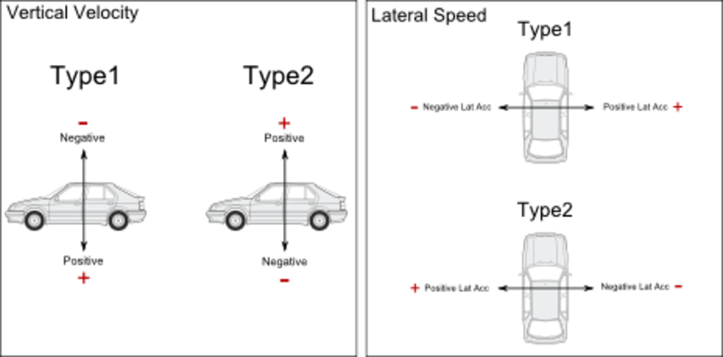
Currently, there are some differences across different units. The image below shows each signing type which could be used for different channels. The two tables below detail which units /software currently use which signing types.
.png?revision=1)
.png?revision=1)
.png?revision=1)
.png?revision=1)
.png?revision=1)
Racelogic
IMU/YAW
Racelogic use a right handed co-ordinate system for the acceleration channels transmitted by the IMU and Yaw rate sensor.
For rotation Racelogic use the following signing convention:
The roll rate is positive clockwise in relation to the x-axis.
The pitch rate is positive anti-clockwise in relation to the y-axis.
The yaw rate is positive anti-clockwise in relation to the z-axis.
Other products
| VB3iSL | VBII SX/SL | VBOX Mini | VBOX Tools | Centerline SW | Brake Test SW | |
|---|---|---|---|---|---|---|
| Lat Acc | 1 | 1 | 1 | NA | NA | NA |
| Long Acc | 1 | 1 | 1 | NA | NA | NA |
| Vertical Velocity | 2 | 2 | 2 | NA | NA | NA |
| Pitch Angle | 2 | 2 | NA | 2 | NA | NA |
| Roll Angle | 1 | 2 | NA | 2 | NA | NA |
| Slip Angle (YAW) | 2 | 1 | 1 | 2 | NA | NA |
| Pitch Rate | NA | NA | NA | NA | NA | NA |
| Roll Rate | NA | NA | NA | NA | NA | NA |
| YAW Rate | NA | NA | NA | NA | NA | NA |
| X Acc | NA | NA | NA | NA | NA | NA |
| Y Acc | NA | NA | NA | NA | NA | NA |
| Z Acc | NA | NA | NA | NA | NA | NA |
| Centerline Dev | 2 | 2 | 2 | 2 | 2 | 2 |
ADAS
| Vehicle Separation | LDWS Firmware | LDWS Software | FCWS Software | |
|---|---|---|---|---|
| Time to Collision | 1 | NA | NA | 1 |
| Range (Remote to Local) - Lat Range (Veh SeP) / Range (LDWS) |
2 | 1 | 1 | NA |
| Range (Remote to Local) - Long Range (Veh Sep) / Range (FCWS) |
2 | NA | NA | 2 |
| Range (Local to Remote) - Lat Range | 1 | NA | NA | NA |
| Range (Local to Remote) - Long Range (Veh Sep) / Speed (FCWS) | 1 | NA | NA | 1 |
| Speed (Remote to Local) - Lat Speed (Veh Sep) / Speed (LDWS) | 2 | 2 | 2 | NA |
| Speed (Remote to Local) - Long Speed (Veh Sep) / Speed (FCWS) | 2 | NA | NA | 2 |
| Speed (Local to Remote) - Lat Speed | 2 | NA | NA | NA |
| Speed (Local to Remote) - Long Speed (Veh Sep) / Speed (FCWS) | 2 | NA | NA | 2 |
Industry Standards
| Channel | ISO | SAE |
|---|---|---|
| Lat Acc | 2 | 1 |
| Long Acc | 2 | 2 |
| Vertical Velocity | 2 | 1 |
| Pitch Angle | 1 | 2 |
| Roll Angle | 1 | 1 |
| Slip Angle (YAW) | 1 | 2 |
| Pitch Rate | 1 | 2 |
| Roll Rate | 1 | 1 |
| YAW Rate | 1 | 2 |
| X Acc | 2 | 2 |
| Y Acc | 2 | 1 |
| Z Acc | 2 | 1 |
Vehicle Attitude
When considering vehicle attitude, Pitch, Roll and YAW/Slip can be used to describe body movement
Pitch
.png?revision=1)
Roll
.png?revision=1)
YAW / Slip
.png?revision=1)
Acceleration – Lateral and Longitudinal
Racelogic units record the acceleration data into the VBO file in the format as indicated below.
.png?revision=1)
Position - Lat / Long
Racelogic uses the signing values as shown below for positional data. This is used when logging data in VBO files, and also in both CAN and RS232 data streams being outputted from VBOX units or Speed Sensors.
.png?revision=1)
You can see in the sample of GPS data below, that the first reported position is ‘+03124.72739 +00060.78906’.
This is indicating +03124.72739 West and +00060.78906 North. This is usually in a minutes format.
.png?revision=1)
Lane Departure Warning Software
Measurement Point Offsets Example
.png?revision=1)
To acquire the offsets, the user will have to physically measure from the centre point of the GPS antenna to the point at which the results should be captured from. These are then applied within the software. Please see example shown below.
.png?revision=1)
Results Signing
Once a results file has been saved out from LDW software in VBO format, it can then be analysed in VBOX Tools. Below is a diagram showing how the signing of the results will behave in relation to whether the vehicle is on the left or right side of each lane.
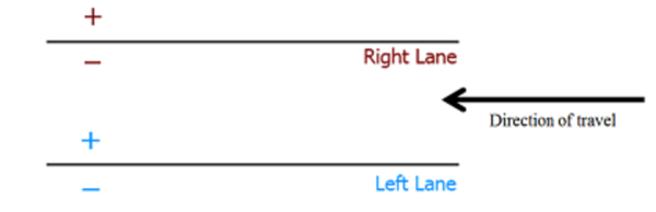.png?revision=1)
Distance to Right Lane: Negative when the right measurement point’s location is left of the right lane.
Distance to Left Lane: Positive when the left measurement point’s location is right of the left lane.
ADAS
Time to collision
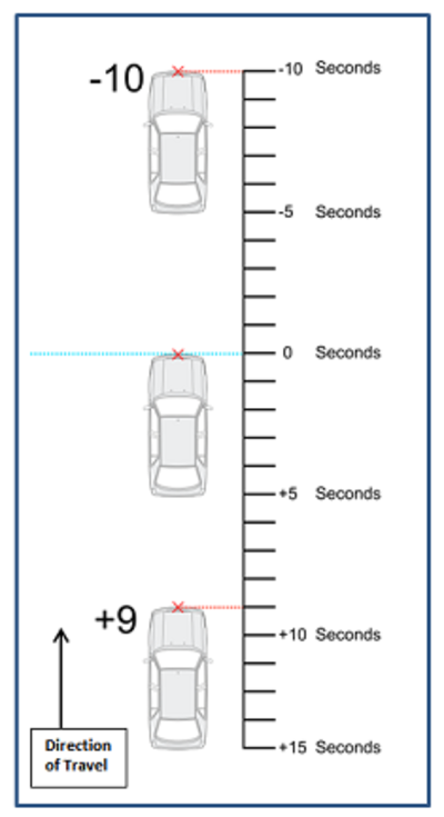
The diagram below shows the signing used on the ADAS time to collision channels.
The red ‘X’ marked on the vehicles, is indicating the set ‘collision point’. This collision point will by default be where the antenna is placed. To change this placement, an offset can be entered.
.png?revision=1)
Antenna offset signing
When setting up a system for ADAS tests, if antenna offsets are entered manually via the VBOX manager then the following sign convention should be used.
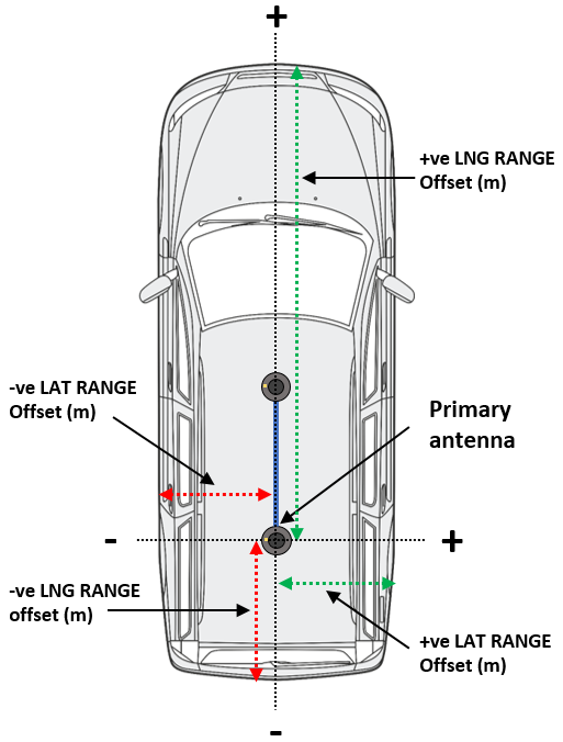
Lateral offset:
When the desired contact point is to the left of the antenna, it is considered a negative offset.
Longitudinal offset:
When the desired contact point is behind the antenna, then this offset is also considered a negative offset.