Brake Testing Measurement and Accuracy

Brake stop distance (using a trigger) is based on two major components, distance and trigger time.
Distance - Speed is an accurate Doppler derived parameter, we integrate this to produce an accurate distance.
Trigger time - VBOX3i for example will capture the trigger event to a nanosecond accuracy, we use this accurate time to interpolate between the GPS samples. This gives us an accurate trigger speed and an accurate trigger time to when the trigger was activated.
Brake stop distance - Using the two components above VBOX will calculate a distance from when the trigger is activated to when the vehicle stops.
The challenge of measuring braking distances accurately
|
There are many factors involved in ensuring brake testing accuracy. The first question you need to ask is which distance do you actually want to measure? It might sound obvious, but in reality it is a complex subject.
There are two basic types of brake test. The first is between two speeds, for example: 100 km/h to 0 km/h. The second is from the initial application of the brakes to a standstill, which is often triggered by a sensor on the brake pedal.
It is very important how and where on the vehicle you measure the braking distance, as this can make a significant difference. Let’s look at the first type of brake test first.
|
 |
Speed to speed brake testing
.png?revision=1)
Differences in speed across the vehicle
|
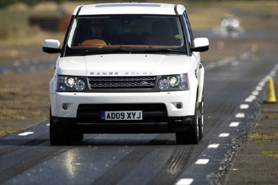
In a test designed to highlight this difference in speed, two identical VBOXs were fitted to the same vehicle. One antenna was placed on the rear of the roof, and the other was placed on the front.
The chart (bottom left) shows the speed from both antennas. The blue trace is the front antenna and the red trace is the rear antenna.
If you examine the highlighted area, which is when the car begins to decelerate, you can see that when one system is measuring 83 km/h, the other system is measuring 82.68 km/h, which is a difference of 0.32 km/h.
|
Two antennas fixed to the front and rear of the vehicle with two VBOX 3i devices |
|
This is not down to inaccuracies of the measuring system, but a real difference in speed relative to the ground over the length of the vehicle.
As shown by the chart (bottom right), if you defined the start speed as 83 km/h, then the rear mounted antenna triggers first and produces a braking distance of 27.17 m, whilst the front mounted antenna triggers later giving a braking distance of 27.01 m.
This is a stopping difference of 16cm, and could produce inaccurate results if the difference in speed along the vehicle is not accounted for.
|
Ideal antenna position when using a single VBOX |
.png?revision=1)
|
Difference of speed between antennas during deceleration |
Difference in relative braking distance between the two antennas |
.png?revision=1)
.png?revision=1)
How to get a consistent brake distance measurement using speed to speed testing
Trigger activated brake test
|
By using a physical switch on the brake pedal, a precise ‘start of braking event’ can be captured which gives a more repeatable result than a speed to speed test.
The position of the antenna is still critical, as the pitching and yawing movement of the vehicle means that different parts of the roof will still travel different distances by the end of the brake stop.
|
Brake pedal switch |
.png?revision=1)
YawFor example, if a vehicle 1.8 metres wide has yawed by 1.5 degrees when it comes to a halt (which is within the typical range for an ABS stop), there would be a 4.7 cm difference in measured stopping distance between the right hand side and left hand side of the vehicle.
To eliminate this measurement inaccuracy, it is therefore critical that the measurement point is on the centre line of the vehicle. This measurement point needs to be as consistent as possible on comparative tests.
PitchDuring the brake stop the vehicle will go from having almost zero pitch angle before the brakes are applied, to a steeply pitched state (4-5 degrees is normal) at the point when the wheels stop turning. Once the vehicle has stopped, the vehicle will then rock backwards to zero pitch angle, moving the antenna on the roof approximately 3-5 cm depending on the vehicle height.
|
Yaw and Pitch angle on a vehicle when braking |
.png?revision=1)
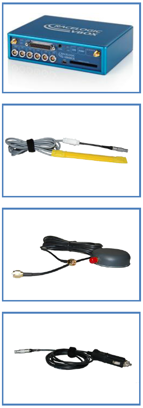
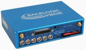
VBOX brake test componentsVBOX 3iVBOX 3i records data at 100 samples per second (100 Hz) using GPS.
It has proved popular with test engineers due to its high level of accuracy. Using a brake pedal mounted trigger input (as shown below) a VBOX 3i will measure the braking distance of a vehicle to within ±1.8 cm.
Brake TriggerBy using an electronic trigger to begin a brake test scenario it enables you to gain consistently comparable results to test the whole braking package (including hydraulics, electronics and tyres). Simply mount the trigger to the brake pedal using elastic strips as shown above.
Antenna (ACS158)For optimum GPS signal reception, ensure the antenna is fitted to the highest point of the vehicle away from any obstructions. Objects in the surrounding area, such as tall buildings or trees, can block GPS signal, causing a reduction in the number of satellites being tracked and decreasing the accuracy of the VBOX.
In-car Power (CAB10)VBOX is simply powered by a 12 V cigar adapter with 2 pin LEMO connection.
|
 |
Brake Testing Setup with VBOX 3i
.png?revision=1) |
|
.png?revision=1)
How accurate is VBOX for brake testing?
Verifying the brake test distance accuracy of VBOX
|
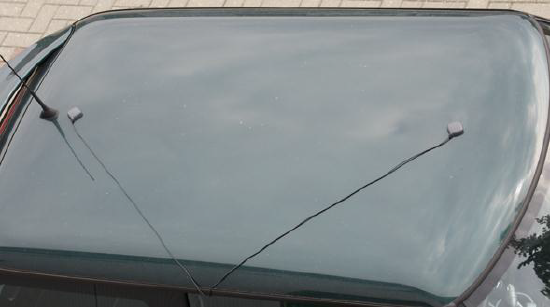
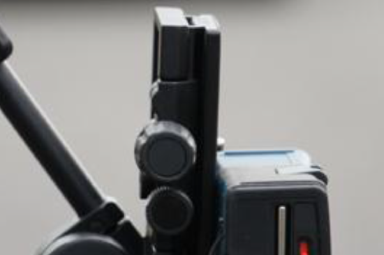
This line has to be at precisely 90 degrees to the direction of travel, as it is difficult to drive the car over exactly the same place every time and we need an accurate start point. We fix a reflective strip along this line, and attach a laser trigger to the side of the vehicle, pointing straight down, to pick up when the car has crossed the line (right). This laser trigger has to be mounted low on the vehicle to reduce any effects from the car pitching as it crosses the line. It is important not to start the braking period until after the vehicle has passed over this line, as the car will begin to yaw under braking, which can cause a lever arm effect on the measurement point. The laser trigger we use has a very low latency of 0.2 ms. This is important because we don’t want to introduce any delays at this critical stage, as the vehicle is travelling at 28 metres per second. The output from the laser trigger is fed into the brake trigger input on the VBOX and replicates the triggering of the pedal sensor, but from a precise known starting line. The vehicle is then driven at 100 km/h up to the line and then the brakes are applied straight afterwards until the vehicle comes to a stop.
It is then a case of measuring the distance that the vehicle has travelled since crossing the line and comparing this with the VBOX measured distance. It is very important to measure from the same point on the vehicle, as the vehicle will not always come to a halt pointing in a perfectly straight line. Therefore we place the GPS antenna over the top of the laser sensor,
and measure from this point.
|
Fixed starter point with laser range finder |
|
Fixed laser range finder |

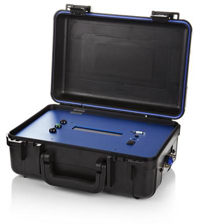
Outlined below is the system used to validate the accuracy of VBOX when measuring braking distances:
.png?revision=1)
| To physically measure the stopping distance, we use a Bosch Laser rangefinder placed on the starting line. This is aimed at a plate which is then placed on the vehicle mounted laser sensor. | 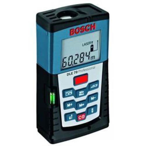 |
.png?revision=1) |
By programming the known GPS position, a Base Station can accurately monitor any variations between the position obtained and its own programmed position. When combined with a VBOX GPS system such as the VBOX 3i, the base station can provide positional accuracy of 95% CEP.
 By combining a VBOX 3i with a Base Station using Real Time Kinematic (RTK) techniques, it enables users to gain repeatable, stable results to within 2cm accuracy.
|