11 - TC Digital Adjuster
Introduction
This manual provides fitting and usage instructions that should allow the unit to be ready for use within minutes.
The Racelogic Traction Control Digital Adjuster is an upgrade to the existing adjuster as supplied with all Traction Control MKII systems, and is only compatible with these systems. If you are unsure as to the system currently fitted to your car please locate the Traction ECU – it must be of the type pictured below. If in doubt please contact Racelogic with the serial number printed on the lid for further assistance.
The Digital Adjuster controls Traction slip level as well as allowing the user to alter certain settings programmed into their Traction Control system.
The Digital Adjuster controls Traction slip level as well as allowing the user to alter certain settings programmed into their Traction Control system. With the relevant firmware upgrade to the ECU, an extended slip range is also available (see Extended Range.)
All alterable settings are those found in the Traction Control software - click here for more information on TC Software.
Installation
The adjuster requires four connections to attain full functionality:
RS232 Serial connection to existing TC Diagnostic lead.
Green wire connects to green wire on existing adjuster loom.
Blue wire connects to blue wire on existing adjuster loom.
Red wire to suitable +12V (ignition switched) –
DO NOT ATTACH THIS TO THE EXISTING RED WIRE ON THE ADJUSTER LOOM: the digital adjuster requires a higher (+12V) power supply than the standard analogue type and will not function if connected to the standard live feed on the adjuster loom.
It is also necessary to ensure that the power supply connection does not go to GND when the car’s engine is cranked. With this in mind one of the best supplies of +12V is that which is connected to the Traction Control ECU itself.
If your Traction Control system is missing the diagnostic lead then the Digital Adjuster can be connected as above, but by omitting the RS232 serial connection it will function as a normal slip controller without any additional features. Diagnostic leads are available as a separate item from Racelogic.
Once the connections have been made it is necessary to site the unit in a convenient place on the dashboard. A Velcro attachment strip is included for this purpose.
Operation
|
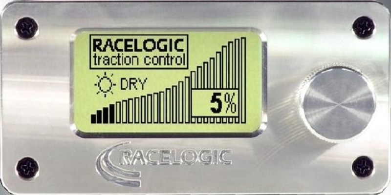
With all connections securely made and the adjuster sited in the best area for viewing whilst driving, begin by starting the vehicle or switching on the ignition. The LCD display will show the Racelogic startup screen. |
.png?revision=1) |
Slip Settings
|
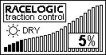
After approximately two seconds the display will default to the slip level setting. |
.png?revision=1) |
|
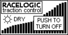
Turning the selector will move the settings 1% at a time and the unit will default to the last setting on power up. The slip level range is from 0% - 25%. In order to turn Traction Control off the selector needs to be turned to 25% when after two seconds this screen will appear. |
.png?revision=1) |
|
Push the button to turn TC off, and this screen will appear: |
.png?revision=1) |
|
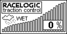
To turn TC back on, push the selector button. The adjuster will default back to the 0% ‘Wet’ setting: |
.png?revision=1) |
Launch Control
Launch control is a function within the Traction Control system designed to automate standing starts to maximise initial acceleration. A secondary rev limit allows the throttle to be floored without over-revving the engine, the car is put into gear and the clutch engaged. The Launch system will control engine revs and wheel speed for the perfect start.
Arming
|
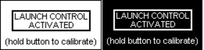
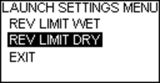
To arm launch control, push and hold the selector button down for a short while. This screen will then appear. Release the button, the system is now in Launch mode. If Launch is activated whilst the slip mode is at 0% ‘Wet’, then the Wet Launch rev limit will be active. If Launch is activated from any other slip level then the Dry Launch rev limit will be active. Please refer to the main Traction Control manual for a further explanation of Wet and Dry Launch modes, and general Launch calibration. |
|
.png?revision=1)
Calibration by Engine Revving
|
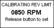
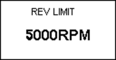
To calibrate the Launch rev limits by revving the engine, keep the button pressed until this screen is shown. |
|
|
As the engine is revved, the RPM speed will alter on the display. Once the desired launch rev limit has been reached, release the selector button – the new rev limit will now be set. To set the Wet Launch Limit ensure this procedure is carried out when the slip display is set to 0% ‘Wet’. To set the Dry Launch Limit ensure this procedure is carried out when the slip display is set to ‘Dry’. Launch Control rev limits can also be programmed by using the configuration feature on the Adjuster. |
|
.png?revision=1)
Launch Fail
|
If the system fails to enter into Launch mode (for instance if the car is not at a complete halt) then the adjuster will display this screen. Subsequent to this the adjuster will default back to the previous slip setting display. |
|
.png?revision=1) =
=Display, Configuration and Diagnostics - Introduction
|
When in slip level display mode, pressing and releasing the selector button will access the display and configuration main menu. |
.png?revision=1) |
|
Use the selector button to scroll up and down the menu options. The three main menu options are Display, Configuration and Try Engine Cuts (Diagnostics). Every menu has an Exit option at the foot of each listing. The Display option allows you to view various Traction Control parameters in a graphical or textual format. The Configuration menu allows you to alter various Traction settings. The Try Engine Cuts menu acts as a diagnostic facility allowing the injector cut interfaces to be tested. |
|
Display
|
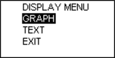
Pressing the selector button once from MAIN MENU -> DISPLAY enters the adjuster into the Display menu. |
.png?revision=1) |
Graph Display
| There are two main display options: Graph and Text. Selecting any of the Graphing options will display the relevant information in a graphical format. The Graph option will display wheel speeds (individually or grouped together), RPM, Cut levels, and Set Speed Range. | 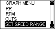.png?revision=1) |
|
Wheels Display - Graph
|
The example below shows wheel speed, with spikes indicating that a wheel speed sensor is intermittently malfunctioning. |
|
.png?revision=1)
RPM Display - Graph
|
The following example shows an RPM trace. |
.png?revision=1) |
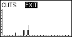
Cuts Display - Graph
|
The following example shows the cut graph, with three injector cuts of increasing severity. |
.png?revision=1) |
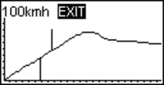
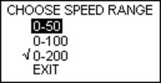
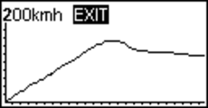
Set Speed Range - Graph
|
The Set Speed Range option alters the graph speed axis to 0-50km/h, 0-100km/h, or 0-200km/h. |
|||
.png?revision=1) |
.png?revision=1) |
.png?revision=1) |
.png?revision=1) |
Text Display
| Choosing the TEXT display mode gives you two options, wheel speed and RPM. | 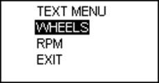.png?revision=1) |
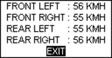
Wheels Display - Text
|
Selecting the WHEELS option takes you to the following wheel speed display. |
.png?revision=1) |
RPM Display - Text
|
Selecting the RPM option displays the current engine speed. |
.png?revision=1) |
Configuration
The digital adjuster allows you to alter many of the settings which exist in the Traction Control software, without the need to use a laptop computer. For example: in the event of changing the car’s wheels (whilst attending a trackday for instance) you will be able to alter the wheel size in order that the system remains calibrated correctly.
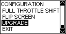
The Configuration menu consists of the following sub-menus: Basic Settings, Launch Control, Configure Wheels, Full Throttle Shift, Flip Screen, and Upgrade.
.png?revision=1) |
.png?revision=1) |
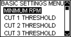
Basic Settings
Selecting BASIC SETTINGS allows the configuration of the Minimum RPM Threshold and ‘Assert At’ cut table percentages (please refer to the Traction Control main manual for an explanation of these settings) and Extended Range operation.
.png?revision=1) |
.png?revision=1) |
Minimum RPM
The Minimum RPM setting represents the lowest engine speed at which the system will make engine cuts, and is altered by turning the selector button. Once the desired setting is shown press the button once to return to the previous screen.
.png?revision=1)
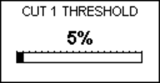
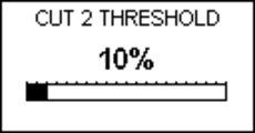
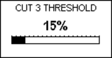
Cut Thresholds
The Cut Thresholds are expressed in percentages, and once each screen is accessed can be altered by turning the selector button. Each click on the selector will increase the level by 1%.
.png?revision=1) |
.png?revision=1) |
.png?revision=1) |
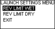
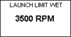
Launch
Selecting the Launch option allows the two Launch Control rev limits to be altered. The limits are increased and decreased in increments of 100rpm. If a limit was last set by engine-rev calibration (see section 2.2.2) it will probably be showing a very specific value (eg 3874rpm). In order to reset the limits to exact 100rpm increments (eg 3700, 3800, 3900) first turn the selector button anticlockwise until the display reads 000rpm – subsequent increases will be in exact 100rpm steps.
.png?revision=1) |
.png?revision=1) |
.png?revision=1) |
.png?revision=1) |
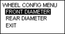
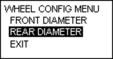
Config Wheels
Selecting the Config Wheels option allows the front and rear wheel diameter settings to be altered in 5mm increments.
.png?revision=1) |
.png?revision=1) |
.png?revision=1) |
.png?revision=1) |
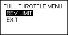
Full Throttle Shift
Selecting the Full Throttle Shift option allows the rev limit for full throttle gear changes to be altered.
.png?revision=1) |
.png?revision=1) |
Contrast
The Contrast function will alter the strength of the display characters on the LCD screen.
.png?revision=1)
Brightness
The brightness function allows the screen brightness to be increased or decreased.
.png?revision=1)
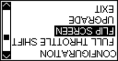
Flip Screen
In the event that you wish to site the adjuster with the control button on the left side of the unit, the display can be rotated through 180 degrees.
.png?revision=1) |
.png?revision=1) |
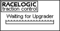
Upgrade
This function is only available to Racelogic Engineers, in the event of a Traction Control ECU having its firmware upgraded to utilise the Extended Range option. Should it be selected in error then the unit will display as follows, but revert to the previous screen after approximately 20 seconds.
.png?revision=1) |
.png?revision=1) |
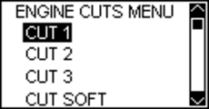
Try Engine Cuts
|
The Try Engine Cuts function is a diagnostic tool, allowing you to check that the Traction Control system is correctly interfacing with the car’s injectors by sending various cut signals. |
|||
.png?revision=1) |
.png?revision=1) |
||
|
Selecting a cut level will result in misfire signals being sent to the injectors. (For a detailed description of these test sequences please refer to the Traction Control manual). The cuts will continue until the selector button is pressed, when the unit exits to the screen above. |
|||
.png?revision=1) |
.png?revision=1) |
.png?revision=1) |
.png?revision=1) |
.png?revision=1) |
Troubleshooting
Below are some potential operation problems and their solutions.
The Adjuster does not power up when the ignition is turned on.
- Check all connections are secure and that the red wire is connected to a +12V power source.
Although the Adjuster shows Slip Control, on pressing the selector button it does not show the menu system.
- Check that the RS232 serial lead is correctly attached. If the problem persists, check the Traction Control system’s communications by using a laptop computer and software.
When calibrating the launch rev limit by revving the engine, only the Wet Launch Limit can be set, even though it is being calibrated from a Dry setting.
- The Adjuster must be connected to a +12V, ignition switched, power source which is not pulled to GND during engine cranking. Launch calibration by engine revving will not work correctly if the adjuster is not connected in this way.