04 - TC How to fit
Fitting RLTC
These articles provide fitting information that should allow fitting the Traction Control within a matter of hours. It assumes however that the person fitting the system has some experience of vehicle electrical wiring. If you are in any doubt about fitting the system yourself please contact a trained auto electrician.
Injector Connections
Information
NOTE: Racelogic Traction Control is only compatible with saturated type injector signals. Ensure that the engine ECU does not utilise pulse width modulation or peak and hold type signals.
Ensure that the injectors are not of a resistance lower than 4 ohms as the traction control cannot cope with the amount of current driving such injectors. In general terms Racelogic Traction Control is only compatible with standard high impedance injectors. If in doubt contact your dealer.
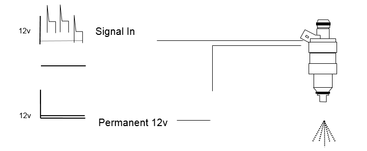
Injector cut works by taking the signal supplied to each fuel injector and feeding it into the Traction Control System. Under normal running, the signal is exactly reproduced firing the fuel injectors as normal. When wheel spin is detected the traction control shuts down each fuel injector independently reducing the power of the engine progressively. The severity of the cut is dependent upon the amount of wheel spin detected and the parameters held within the Traction Control Unit.
By inspecting the fuel injectors of your vehicle you will see that two wires are connected to each one. One of the wires supplies +12 V whereas the other supplies a 12V signal going down to GND to fire the injector. It is these “signal” wires that have to be located and connected to the Traction Control.
Grouped or Sequential Injectors
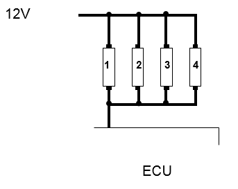
| Sequential | |
|
This image below shows fuel injectors that fire sequentially. This means that the ECU fires each injector individually. The traction control can be interfaced at the ECU. All modern cars use sequential injection. |
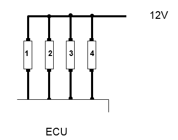 |
| Grouped | |
|
This image shows that all four of the fuel injectors are fired off one signal from the ECU. This is more common in older cars. The traction control needs to be able to control individual injectors, so it will need to be interfaced where the signal splits to each injector. The signal is sometimes split just outside the ECU or at the injector under the bonnet, in which case extra wiring may be needed. |
 |
Locating Signal Wires
The signal and 12V wires have to be connected to the correct pin of the fuel injector so you have to find the “polarity” of the fuel injection system before fitment. The polarity can be identified using a number of methods.
- Wiring Diagrams - If you have a wiring diagram of the vehicle trace each of the signal wires from the engine control unit (ECU) to each of the fuel injectors, the wiring diagram will normally indicate colour codes. The 12V feed wires will be linked together and will generally have a common colour code. If you have books such as the “Autodata - Fuel Injection” series these can help in identifying the polarity of a vehicles fuel injection system.
- Colour Coding - If you have no wiring diagrams you can identify the polarity by looking at the wiring to the fuel injectors. If each of the fuel injectors is fed by a common wire of one colour this will be the 12V feed, the remaining wires should all be different colours and will be the signal wires.
- Resistance Testing – On the majority of cars the 12V power side of the fuel injectors are all linked together. Place the multi-meter on one injector and check with the next injector. Set the multimeter to measure resistance and ensure the resistance between the same sides of the injector is around 1 ohm (i.e. the resistance of the wire joining the 12 v supply)
.jpg?revision=1)
Having located the signal wires, note the colour codings for the fuel injection system down for future reference.
Connecting the Injector Cut
Once the polarity of the fuel injection system has been found the signal wires feeding each fuel injector must be cut and the injector cut loom connected.
Injector Cut Fitting
We highly recommend using the 8 way multi-lock connectors when interfacing the traction control with the vehicle, by doing this the car can easily be returned to standard.
Connect each wire from the Traction Control Loom to each of the injector signal wires as shown below
- Cut the signal wire and strip each end exposing the cores.
- Crimp a male contact to the ECU side and a female contact to the Injector side.
- Insert into the appropriate 8 way multi-lock connector making sure that when the connectors are placed together, the connection is remade.
- Repeat the above process for each of the signal wires.
The injector cut inputs and outputs wires have the following colours.
| Traction Control Inputs and Outputs (6 Cylinder, located on connector A) | |||
| Input Pin No | Signal Input (Colour) | Output Pin No | Signal Output (Colour) |
| A – 8 | Red | A – 11 | Red/Black |
| A – 9 | Orange | A – 12 | Orange/Black |
| A – 22 | Grey | A – 25 | Grey/Black |
| A – 23 | Green | A – 24 | Green/Black |
| A – 10 | Yellow | A – 13 | Yellow/Black |
| A – 21 | Pink | A – 26 | Pink/Black |
| Additional Inputs/Outputs (8 cylinder, located on diagnostic connector B) | |||
| B – 1 | White/Red | B – 8 | Green/Red |
| B – 2 | Orange/Red | B – 9 | Grey/Blue |
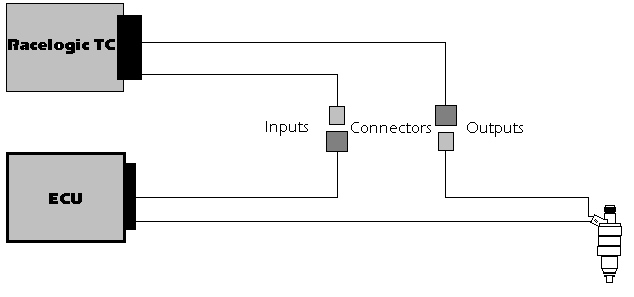
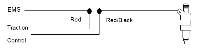
For example channel 1 of the traction control should be connected as shown below.
ABS Connection (ABS type Traction units only)
Information
The easiest method of linking into the ABS sensors is to locate the controller. This may look like an engine ECU or be combined with the ABS pump.
|
ABS Pump and Controller |
ABS Unit |
.png?revision=1)
.jpg?revision=1)
Most ABS sensors are passive inductive sensors that give a signal when metal passes near them. Resistance of sensors varies from approximately 800 - 1500 ohms. Sensors usually have two wires each, which account for eight wires feeding the ABS unit. These wires have to be located and four wires from the traction control have to be connected to one side of each sensor. Deciding which wire to connect to is dependent upon the type of sensor used.
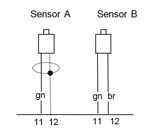
ABS Sensors
.png?revision=1)
In the first example sensor A, one of the wires is connected to the shielding of the cable (pin 12), the traction control wire must be connected to the wire connected into pin 11. In the second example sensor B, both wires carry signals to the ABS, therefore the traction control can be connected to either wire.
Note that if you do not obtain a signal by connecting to either side of the sensor it may be necessary to identify the positive and negative sides of the sensor. Once this has been done tie the negative sides to the same ground as the Traction Control is connected to, then connect each positive side to the relevant Traction Control wheel speed input. If you are at all unsure consult an automotive electrician.
Locating Wheel Speed Sensor Wires
The wires can be found using a number of methods.
- Twisted Pairs and 2 core wire – The sensor wires will be fed back to the controller and are normally then identified as a twisted pair or 2 core cable.
- Wiring Diagrams - If you have a wiring diagram of the vehicle, trace each of the sensor wires to the ABS unit, the wiring diagram will normally indicate colour codes. If you have books such as the “Autodata - Anti Lock Braking Systems” series these can help in identifying the wiring. (Contact Racelogic if you do not have one).
- Multimeter Resistance Setting – Switch a meter to “Resistance” and test each of the wires leading to the ABS unit, Diagram 8. Ensure the connector is plugged in when you are doing this. Wheel speed sensors will generally have a resistance of between 800 – 1.2 K ohms.
- Oscilloscope – Once likely wires have been found, jack the car up so a wheel can be spun freely. Probe each side of each pair until a signal is found. Typically the signal will be a sinewave.
.png?revision=1)
Having completed the test, write down the wiring colours corresponding to each wheel speed for future reference.
Connecting Traction Control ABS Wires
The 4 traction control ABS wires are coloured Red, Blue, Yellow and Green and form the 4 core shielded cable.
Connect each wire from the traction control loom to each of the 4 ABS sensor wires as follows.
- Strip back the shielding of the ABS wire exposing the cores.
- Tin the cores using the soldering iron and solder.
- Strip back the shielding of the traction control wire.
- Tin the cores using the soldering iron and solder.
- Solder the traction control Wire to the ABS wire.
- Cover the joint with insulation tape.
The ABS connections can be tested using either a laptop computer or the diagnostic facility on the traction control.
Self-Fit Sensors (Wheelspeed sensor units only)
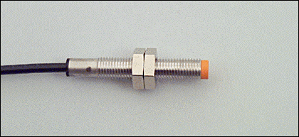
Sensor
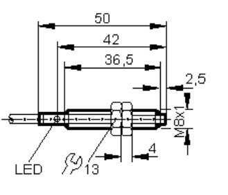
Shown below is a wheel speed sensor as supplied for use with wheel speed type Traction control units.
Pickup Methods
The exact method used to locate and trigger the wheel speed sensors is absolutely critical to the correct operation of the Traction Control System. There are a number of different ways to construct the pick-ups, the slotted disc method, the toothed wheel, hole detection and bolt detection.
Sensor’s must be rigidly mounted so no large vibrations occur that will move the sensor head more than 0.5mm away from the reference points and the head must be at 90° to the surface. If a sensing plate / disc is used, it must not be warped or mounted at an angle that would cause the distance between the head and disc to change by more than ±0.5mm. The material used for the reference must be of a ferrous type, if in doubt, check to see if it attracts a magnet.
The reference can be painted or plated. To achieve the best results, the sensor should be at least 40mm away from the center of rotation of the reference. The number of reference holes / teeth / slots should be between 4 & 120, there can be a difference from front to rear as this can be programmed in at a later stage.
|
Slotted disc |
.png?revision=1) |
|
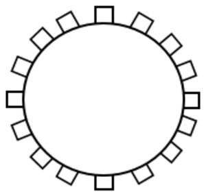
Toothed wheel |
The teeth have to be clean without any scratches in the metal that would cause false signals at high revolutions. The minimum size of teeth is 2mm across. |
| Hole detection | The reference holes have to be bigger than the head of the sensor, bigger ones are preferable. |
| Other |
If none of the methods above are practical, then it is worth noting that the sensor can pick up from evenly spaced fixing bolts, or cooling vanes in a brake disc etc. It is recommended that the sensors are shielded from any stray stones thrown from the wheels and kept well away from any other source of electrical noise (HT leads, radio leads, coil power supply leads etc.). Racelogic have fitted numerous cars and have found that the best method of fitment is to pick up from the back of the wheel fixing bolts. |
.png?revision=1)
Sensor Fitting
The sensor is mounted by the two nuts that are supplied with the sensor. When tightening the sensor, care has to be taken as the sensor can be split in half or cross-threaded if over tightened. It is recommended that a thread lock be used to stop the nuts becoming loose.
Sensor Gapping
The sensor will work up to a range of 2mm. Try to gap the sensor to 1.5mm away from the pickup point, this will allow for any movement.
Power up the traction control System and keep moving the sensor closer until the LED on the sensor is illuminated.
NOTE – If you are picking up from a wheel hub etc, it is very important that the gap on the sensor does not move when the car is under hard cornering. This could cause the gap to either close up or open up. This could cause the sensor to drop out and the traction control to stop working correctly.
Sensor Checklist
The LED on the sensor must flash as the wheel is rotating.
Sensor face must be at 90° to the surface.
Over one revolution, the sensor to plate distance must not vary more than ±0.5mm.
Wheel speed Wire corners
The system is programmed at the factory to reflect the sensor orientation shown below.
.png?revision=1)
Connecting Sensors
Once the sensors have been fitted each of the four wires must be run to the sensors. Each wire has two cores with red and blue shielding. Connect each wire to the sensor as follows.
- Run each wire to the sensors.
- Place a length of Heat shrink over the wire.
- Strip back the insulation exposing the two cores.
- On the red wire crimp the female contact, and on the blue wire crimp the male.
- Push the crimps into the Sure Seal (waterproof rubber connector that comes with the sensors), red to pin 1 and blue to pin 2, ensuring they are pushed all the way in.
- With a heat gun shrink down the heat shrink.
| Sure-Seal Pin | TC Colour | Sensor Colour |
|---|---|---|
| 1 | Red | White |
| 2 | Blue (GND) | Black |
RPM, Power and Ground Connections
Ignition Switched Supply
The red wire (Pin 2) with inline fuse should be connected to a suitable ignition switched 12V source. A suitable 12V source can be found using any of the following techniques.
- Wiring Diagrams - If you have a wiring diagram of the vehicle, find an ignition switched 12 V feed.
- Multimeter – Select “voltage test” on the meter and probe wires that could supply an ignition feed 12V. Once a suitable feed has been found, crank the car and ensure it doesn’t go to GND during cranking.
- Injectors – Trace the 12V side of the fuel Injectors back to either the relay box or the ECU.
Once a suitable feed has been found, follow the procedure below for connecting the 12V supply to the 12V input of the traction control.
- Strip back the insulation of the 12V wire exposing the cores.
- Tin the cores using the soldering iron and solder.
- Strip back the insulation of the traction control wire.
- Tin the cores using the soldering iron and solder.
- Solder the traction control Wire to the 12V wire.
- Cover the joint with insulation tape.
- MAKE SURE THIS 12V FEED DOES NOT DROP TO GND DURING CRANKING OF THE ENGINE. Again this can be checked with the use of an oscilloscope. In the example below the 12 v supply drops to 7 v when the engine is cranked, which is fine:
.jpg?revision=1)
RPM
The Black/White wire (Pin 18) should be connected to a suitable RPM signal. A suitable signal would be either 0 –12 Volts or 0 – 5 Volts.
A suitable RPM signal can be found using any of the following techniques:
- Wiring diagrams - If you have a wiring diagram of the vehicle find an RPM signal.
- Tachometer – There is usually an RPM signal leading to the back of the dashboard. (Highly Recommended)
- Coil signal – note, if the car has twin coils the cylinder value in the traction control menu may need to be changed. e.g. 6 Cylinder engine, twin coils, set cylinders to 3 if RPM is picked up off one coil.
- Diagnostic Connector – Some cars have a diagnostic connector, these will normally have a RPM signal. e.g. pin1 on BMW Diagnostic Socket.
- ECU – most cars will have an RPM signal coming out of the ECU.
Once a suitable RPM signal has been found, follow the procedure below for connecting the RPM wire to the RPM input of the traction control.
- Strip back the insulation of the RPM wire exposing the cores.
- Tin the cores using the soldering iron and solder.
- Strip back the insulation of the traction control wire.
- Tin the cores using the soldering iron and solder.
- Solder the traction control Wire to the RPM wire.
- Cover the joint with insulation tape.
The RPM connection can be tested using either a laptop computer or the diagnostic facility on the traction control. This is explained in Section 7.2 Diagnostic Modes.
Fitting the traction control switch
The traction control switch will need to be mounted on the car where the driver can adjust it while driving. The adjuster connects to a three core cable from the main traction loom. This cable consists of a red, a green and a blue wire.
If you have purchased a system with a Digital Adjuster please refer to the separate fitting and usage instructions.
Manual Slip Adjuster installed in a Holden HSV
.jpg?revision=1)
Launch Button and Manual Slip Adjuster installed in a Nissan 300ZX
.png?revision=1)