01 - TC Introduction
These articles provide fitting information that should allow fitting the Traction Control within a matter of hours. It assumes however that the person fitting the system has some experience of vehicle electrical wiring. If you are in any doubt about fitting the system yourself please contact a trained auto electrician.
How it works
The Racelogic Traction Control System works by monitoring the vehicle’s wheel speeds, looking for differences between them. When the system detects an excessive difference in wheel speeds above programmable thresholds, fuel cuts of varying severity are initiated to progressively reduce the power of the engine, reducing wheel spin and maximising acceleration.
Connecting the system involves interfacing with the vehicles existing ABS sensors or using our own wheel speed sensors to provide the wheel speed inputs and breaking each of the signal wires supplying the fuel injectors. This allows the Traction Control to cut fuel when wheel spin has been detected.
A Schematic of the complete Traction Control System can be found here.
Inventory of the traction control kit
| Manual | TC Switch |
|---|---|
| Software disc | Heatshrink |
| TC Box | 2 x 8 Way Multilock Connector Male |
| TC Loom | 2 x 8 Way Multilock Connector Female |
| Diagnostic Loom | 18 x Male Contacts |
| Diagnostic Plug | 18 x Female Contacts |
.jpg?revision=1)
 |
.jpg?revision=1) |
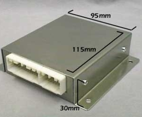
Standard TC box
Recommended Fitting Tools
- Screw Driver - Cross Head
- Screw Driver - Flat Blade
- Wire Cutters
- General Purpose Crimp Tool
- Wire Strippers
- Soldering Iron
- Solder
- Electrical Tape / Heatshrink Tubing (4/2 mm Shrink Ratio)
- Assorted Tie-wraps
- Multi-Meter
The tools listed above are the basic requirement for fitting Traction Control, additional tools may be required for specific vehicles.