02 - MICIN Analogue Inputs
All of the analogue inputs are non-opto isolated 10 bit 0 - 14.5 V inputs. They are all single-ended inputs that share the common ‘A Ground’ and a 4 MΩ input impedance means the unit can be used for direct connection to existing pots on a car.
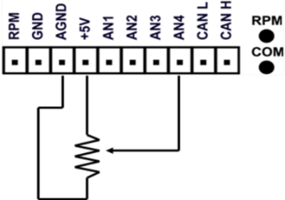
An example of how to connect an isolated individual potentiometer is shown below.
.png?revision=1)
Connecting to a potentiometer already installed on a car, such as a throttle potentiometer, would only require the output signal from the pot and the earth to be connected to the MICIN01.
RPM input
The diagram below shows a typical connection to the ‘low tension side of an ignition coil for RPM pickup.
.png?revision=1)
Sensor Information
Racelogic does not recommend any particular sensors for use with our products, due to the vast variety of applications they can be used in. If any customers want to know if a sensor they have (or intend to purchase) will be compatible, we are happy to advise them on this. If you have a datasheet for the sensor, then we can advise if this is suitable, and how to connect this to the Micro Input Module.
Please feel free to raise a ticket with our support team for further help.
Some generic details are below which should be helpful for most situations.
When using a passive sensor which does not require a direct power feed, then this should be connected to any single AN Input and AGND.
For resistive sensors, take the +5 V signal from the Micro Input Module, via a pull up resistor (1k will be suitable for our application) and voltage out to any AN Input on the Micro Input Module.
For frequency based sensors, the RPM input (Frequency counter) will need to be used, as well as a connection to GND.